Tritium Safety Issues
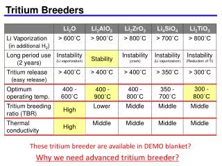
Tritium Safety Issues. David Petti March 7, 2001 Tritium Town Meeting Livermore, CA. Outline. Releases during normal operation Releases under accident conditions Tritium confinement Inventory guidelines Number of barriers Implementation concerns for MFE and IFE

Tritium Safety Issues
E N D
Presentation Transcript
Tritium Safety Issues David Petti March 7, 2001 Tritium Town Meeting Livermore, CA
Outline • Releases during normal operation • Releases under accident conditions • Tritium confinement • Inventory guidelines • Number of barriers • Implementation concerns for MFE and IFE • Deflagration/Detonation Risk • Contamination Issues • Ventilation • Maintenance
Release during Normal Operation • DOE Fusion Safety Standard requires less than 0.1 mSv/yr (10 mrem/year), a factor of 10 below regulatory standards (application of ALARA principle) • For a typical site with a 1 km site boundary, this translates into: • 20 to 30 Ci/day up the stack as HTO • 2 to 3 Ci/day release at ground level as HTO (which is the most likely location for leakage from power conversion system) • Factor of ten higher if HT • Tritiated liquid releases can be much more stringent depending on the specific state
Release Under Accident Conditions • DOE Fusion Safety Standard states the facility must meet a dose limit of 10 mSv (1 Rem) under worst postulated accident to avoid the need for public evacuation • We used to apply average weather conditions for such an assessment per DOE Fusion Safety Standard • More recent DOE emergency planning guidance is now very clear that we must use conservative weather!
Release Under Accident Conditions • For a typical site, with a 1 km site boundary, the 10 mSv dose converts to the following release limits for grams of tritium as HTO: Weather Average Conservative Elevated 1500 g 150 g Groundlevel 150 g 15 g 15 g of tritium release will be extremely difficult to meet! It may mean greater confinement.
Tritium Confinement • Per US DOE Fusion Safety Standard, confinement of radioactivity is the primary public safety function: • Radioactive and hazardous material confinement barriers of sufficient number, strength, leak tightness, and reliability shall be incorporated in the design of fusion facilities to prevent releases of radioactive and/or hazardous materials from exceeding evaluation guidelines during normal operation or during off-normal conditions. • In the design of confinement barriers, the principles of redundancy, diversity, and independence shall be considered. Specifically, in the case of multiple barriers, failure of one barrier shall not result in the failure of another barrier if evaluation guidelines could be exceeded. Redundancy and diversity shall be considered in the total confinement strategy if new or untested components of a barrier are used.
Confinement Implementation • Where are the major inventories? • How many barriers? • How much inventory are you confining? • What about the penetrations? How do you implement confinement barriers there? • What are the testing requirements for the barriers?
Major Inventories • Chamber • Co-deposited material • Implanted or bred in PFC • In dust/debris • Cryopumps • Tritium Plant • ISS was the component with the highest inventory in ITER EDA • Tritium Target Factory (IFE) • Diffusion chambers and target preparation
Number of barriers • The number of barriers should be based on the vulnerable inventory and reliability of confinement barriers such that the risk based design dose targets are not exceeded (i.e., work backwards from dose targets) • A highly reliable robust barrier would have a breach probability of ~ 10-3 per challenge. A less reliable barrier would have a breach probability of ~ 10-1 to 10-2 per challenge. (Actual reliability depends on the design and the postulated challenges to the barrier) • It is a design decision to determine how many barriers are needed. More reliable barriers have more stringent design criteria than less reliable barriers and would cost more to design, build, certify, maintain and survey. • In general, lower vulnerable inventories require fewer barriers. As a rule of thumb, in ITER less than 100 to 150 g would require one highly reliable barrier or two less reliable barriers. 100 g to 1 kg would require two highly reliable barriers • Segmentation of the inventory is a good way to minimize the number of required confinement barriers, but it may increase facility foot print and add components like valves to the design
Confinement in the ITER-EDA design (1 kg of tritium in plasma chamber)
Confinement in MFE Penetrations • Probably most important for fusion given large number of penetrations attached to the plasma chamber in both MFE and IFE • In MFE, the primary confinement boundary in many cases followed the vacuum boundary. Valves that were needed for leak testing also became parts of the confinement boundary. • In some cases such as HCD, windows were also part of the first confinement barrier and the second barrier was a fast-acting valve downstream in the system • An extra valve was inserted in the pumping lines between the plasma chamber and tritium plant to prevent any tokamak off-normal event from propagating into the tritium plant • Implementing the redundancy, diversity and physical separation requirements was most difficult in some of the penetrations because of the physical layout of the system
Confinement in IFE Penetrations • Our goal is to use existing systems or components to implement safety functions so as to avoid adding on components and systems • For confinement, we try to confine as close to the source as possible because of the cost associated with large confinement buildings or structures • For IFE, with all of the beam openings, the nearest physical boundary up the beam lines may be 50 m away. Control of such a large confinement boundary would be very difficult and problematic. • The use of fast acting valves in the beam lines may be needed to implement confinement in IFE systems. This is being examined as part of the ARIES-IFE study
Testing Requirements • From the DOE Fusion Safety Standard: • Consistent with the safety analysis, the design of confinement barriers shall specify an acceptable global leak rate under off-normal conditions, taking into account the vulnerable inventories of radioactive and hazardous materials, and the potential energy sources available to liberate such inventories. Any confinement barrier, including equipment, penetrations, seals, etc., relevant to the establishment of an acceptable leak rate shall be designed and constructed in such a way as to enable initial and periodic leak testing • Such testing requirements are used in current fission reactors, university reactors, and DOE nuclear facilities
Deflagration/Detonation Risk Detonation Deflagration • Most severe form of explosion (collapse strong buildings, denude trees) • Combustion wave propagates at supersonic velocity, between 1500 and 2000 m/s • Pressures 15 bar and higher are possible • High ignition energy, kJ • Most common mode of explosion, can be severe (break glass, cause shrapnel, topple buildings • Combustion wave propagates at subsonic velocity, between 1 and 1000m/s • Pressures from mbar to 8 bar • Low ignition energy, mJ H2 + air --> explosion
Deflagration/Detonation Risk • Tritium, as a hydrogenic species can pose a deflagration or detonation risk • Hydrogen deflagration concentration is 4 to 75% at STP. Detonation concentration is 18 to 59%. • Limits are set on the amount of hydrogenic species in the plasma chamber and tritium plant • Analysis of response of systems was performed in ITER to examine worst credible deflagration/detonation • For ITER, hydrogen generation from Be/steam interactions were much more important than the in-vessel tritium inventory • Tritium inventory on cryopumps can be a concern for small tokamak machines such as FIRE (set the regeneration time) • Currently examining the issue for the IFE Target Factory
Tritium Contamination • Safety requirement is to minimize spread of contamination as much as possible • Secondary confinement in process systems (e.g. in the gloveboxes in the tritium plant) usually have glovebox cleanup systems • All rooms/areas where high levels of tritium contamination are expected in an off-normal conditions usually have emergency atmospheric detritiation systems • The plasma chamber and the heat transfer vaults may need a maintenance detritiation system to reduce levels if human entry is required • Tritium contamination is an important consideration in the design of the HVAC systems for the facility and in the development of maintenance approaches in the plant • Minimizing spread of contamination is a strong design driver for occupational safety
Summary Tritium safety issues • during normal operation --> permeation and leakage • during off-normal operation --> inventory minimization, confinement, deflagration risk, leak testing • and during maintenance --> minimizing contamination are strong design drivers for fusion systems
Fusion Safety Chemical Reactivity Experiments Home of the STAR Facility at the Idaho National Engineering and Environmental Laboratory W brush samples Safety and Tritium Dust/Debris Characterization Applied Research Fusion Safety Mobilization Testing TFTR DIII-D C-MOD STAR Mo alloy samples after exposure to air NOVA Tore Supra Molten Salt Tritium/ Chemistry Pot Experiments Be sample after exposure to ion beam Tritium Plasma Experiment TPE Plasma Tritium Uptake in Materials