Download
1 / 40
420 likes | 1.14k Vues
Lifts: An Application to Electrical Drives. Prepared by: Al Harith Auda (0060772) Nazeeh Ammari (0076411) Iskander Imseeh (0077601). Brief history of Elevators.

E N D
Lifts: An Application to Electrical Drives Prepared by:Al HarithAuda (0060772) Nazeeh Ammari (0076411) IskanderImseeh (0077601)
Brief history of Elevators • Elevators are not exclusive to modern life, the first reference to an elevator is in the works of a Roman architect, who reported that Archimedes built his first elevator probably in 236 BC. • In the middle 1800s, there were many types of elevators that carried freight. Most of them were hydraulic. The first hydraulic elevators used a plunger below the car to raise or lower the elevator. A pump applied water pressure to a steel column inside a vertical cylinder. Increasing the pressure caused the elevator to ascend. • In 1852, Elisha Otis (American Industrialist) introduced the safety elevator, which prevented the fall of the cab if the cable broke. The design of the Otis safety elevator is somewhat similar to one type still used today.
Main Structure An elevator consists of: • Car (passenger’s room). • Pulleys. • Gears used to change the speed. • Electrical bidirectional motor. • Brakes. • Counterweight. The figure in the next slide shows the components of an elevator.
Types of Elevators • There are many types of elevators, we will briefly describe four of them in this lecture with focus on the Traction Elevator. Pneumatic Vacuum Elevators These operate without cables or pistons and can be installed more easily and quickly than their alternatives since their housing is composed of prefabricated sections which are considerably narrower than conventional lift shafts. These sections are transparent and afford the passenger a near 360° view. Other notable features of the vacuum elevator are as follows: • Installation within one to two days • Two to four stops for residential, marine, and stage use (35 ft total rise) • Ideal for new and existing homes due to the minimal space needed to fit the elevator • Self-supporting structure: the elevator can rest on any existing ground floor
Hydraulic Elevators • Conventional hydraulic elevators: They use an underground cylinder, are quite common for low level buildings with 2-5 floors (sometimes but seldom up to 6-8 floors), and have speeds of up to 200 feet/minute (1 meter/second). • Holeless hydraulic elevators were developed in the 1970s, and use a pair of above ground cylinders, which makes it practical for environmentally or cost sensitive buildings with 2, 3, or 4 floors. • Roped hydraulic elevators use both above ground cylinders and a rope system, which combines the reliability of inground hydraulic with the versatility of holeless hydraulic, even though they can serve up to 8-10 floors. • The low mechanical complexity of hydraulic elevators in comparison to traction elevators makes them ideal for low rise, low traffic installations. The main disadvantage is their lower efficiency – with no counterbalancing, they require more power to operate. • The design of a hydraulic elevator is shown in the next slide.
Climbing Elevator • A climbing elevator is a self-ascending elevator with its own propulsion. The propulsion can be done by an electric or a combustion engine. Climbing elevators are used in guyed masts or towers, in order to make easy access to parts of these constructions, such as flight safety lamps for maintenance.
Geared Traction Elevator • Geared traction machines are driven by AC or DC electric motors, they use gears to control mechanical movement of elevator cars by “rolling” steel hoist ropes over a drive sheave which is attached to a gearbox driven by a high speed motor. • These machines are generally the best option for basement or overhead traction use for speeds up to 500 ft/min (2.5 m/s). • In order to allow accurate speed control of the motor, to allow accurate leveling and for passenger comfort, a DC hoist motor powered by an AC-DC motor-generator set was the preferred solution in high-traffic elevator installations for many decades.
Gearless Traction Drive • Gearless traction machines are low speed (low RPM), high torque electric motors powered either by AC or DC. In this case, the drive sheave is directly attached to the end of the motor. • Gearless traction elevators can reach speeds of up to 2,000 ft/min (10 m/s), or even higher. • A brake is mounted between the motor and drive sheave (or gearbox) to hold the elevator stationary at a floor. This brake is usually an external drum type and is actuated by spring force and held open electrical. • a power failure will cause the brake to engage and prevent the elevator from falling. • The gearless and geared design are shown in the next slide.
Configuration of Geared traction lift Configuration of Gearless traction lift
Traction Drive and Roping System • A roping system is used to attach the motor/gear reducer, the elevator car and the counter weight. • There are many different kinds of arrangements that can be used. In one possible arrangement, such as shown in the figure below, both ends of the elevator rope are anchored to the overhead beam. Both the elevator car and the counter weight are attached to free moving pulleys. The traction drive is attached to a stationary pulley.
Traction Drive and Roping System • The traction drive is the method of converting the input mechanical power (in this case the turning of a shaft) into useable mechanical power in the system (the vertical movement of the elevator). The friction between the ropes and the sheave grooves, which are cut on the pulley, initiates the traction force between the traction drive and the rope. • When the traction drive is rotated power is transferred from the traction drive to the elevator car and counter weight. Power is only needed to move the unbalanced load between the elevator and the counterweight.
Roping Systems • A variety of roping systems can be employed dependant on the particular conditions of each • installation (e.g. machine positioning, rated load and speed, available space, etc.). Examples of commonly used roping systems are shown in the figure in the next slide.
Gears The elevator is composed of a motor and, most commonly, a gear reducer system, which functions as follow: • Decrease the rotational speed of the traction pulley, By decreasing the rotation speed, with the use of a gear reducer, we are also increasing the output torque, therefore, having the ability to lift larger objects for a given pulley diameter. • Change the plane of rotation.
Motors The motor component of the elevator machine can be either a DC motor or an AC motor, each has it’s advantages: DC motor: • Has a good starting torque. • Ease of speed control. AC motor: • More regularly used because of its ruggedness and simplicity.
Electrical Brake System • A resistor is connected in series with the motor through a switch • after closing the switch the electrical current fights its way through the resistor to get back to the generator, the energy is lost as heat in the resistor.
Brake System • The most common elevator brake is made up of a compressive spring assembly, brake shoes with linings, and a solenoid assembly. • When the solenoid is not energized, the spring forces the brake shoes to grip the brake drum and induce a braking torque. • The magnet can exert a horizontal force for the break release. • The break is pulled away from the shaft and the velocity of the elevator is resumed, the system is explained in the following figure.
Modes of Operation In an elevator system, it’s possible to regenerate some (if not all) of the power consumed, the elevator has four modes of operation: • First quadrant (forward motoring): In this mode, the system is consuming power, where both the torque and the speed are positive. • Second quadrant (forward braking): In this mode of, the system is regenerating (supplying) power, where the torque is negative and the speed is positive. 3. Third quadrant (reverse motoring): In this mode, the system is consuming power, since both torque and speed are negative and their product is positive. • Fourth quadrant (reverse braking): In this mode, the system is regenerating power again, since the torque is positive and the speed is negative. The next slides show these modes in the four quadrants for better demonstration.
INTRODUCTION TO ELECTRIC DRIVES - MODULE 1 T Torque-speed quadrant of operation 1 2 • T -ve • +ve Pm -ve • T +ve • +ve Pm +ve 3 4 • T -ve • -ve Pm +ve • T +ve • -ve Pm -ve
INTRODUCTION TO ELECTRIC DRIVES - MODULE 1 Te m m Te Te T Te m m 4-quadrant operation • Direction of positive (forward) speed is arbitrary chosen • Direction of positive torque will produce positive (forward) speed Quadrant 1 Forward motoring Quadrant 2 Forward braking Quadrant 3 Reverse motoring Quadrant 4 Reverse braking
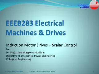
Speed Control In an Elevator System • The Adjustable Speed Drive consists of a power electronic converter driving the three -phase induction motor coupled to a gearbox. • The power electronic converter has a variable-voltage variable-frequency output, and for the elevator, it is a commercial three phase Pulse Width Modulated – Voltage Source Inverter with a single-phase diode bridge rectifier input. • The elevator position feedback signal back to the controller is provided by an inductive proximity sensor (a sensor used to detect the position of the elevator).
PWM Converters: • They rectify ac signal to dc signal. • They have inherent rectifying and regenerating capabilities and improve the dynamic performance of the whole system. PWM Inverters: • They make the ride much smoother by precisely adjusting speed control with voltage and frequency regulation. • The inverters also include the latest low-noise power modules to make the ride even quieter.
The voltage-fed three-phase pulse width modulation (PWM) rectifier is adopted so that dc bus voltage regulation, bidirectional power flow, and controllable power factor with reduced input current harmonics are possible.
Some additional hardware is adopted for the high performance and reliability of the whole drive system. • It consists of a filter inductor at the inverter side and an RC terminal at the motor side. • The filter inductor is designed for the reduction of audible noise, caused by sharp dv/dt ratio. • The RC terminal at motor side is designed for decreasing dv/dt at the motor terminal and then preventing insulation failure of the motor.
Power Considerations • Once the power is transferred through the gear reducer the output speed will be reduced and the torque will be greater. • The overall power will be slightly lower as the system is not 100% efficient. Tension on the rope from the elevator pulley is equal to the weight of the elevator, We. The tension on the rope from the counter weight is Wc.
Passenger Demand • One important input is passenger demand, which varies during the day. • The Figure on the next slide shows a classic traffic pattern during the day in an office building. • At the start of the day, there is usually a larger number of up traveling traffic (up peak), as travelers arrive at the building. • At the end of the day outgoing (down peak) traffic demand dominates. • In the middle of the day, there are other, smaller, up and down peaks, as building occupants leave and arrive fromlunch. • Between these peak periods, during the morning and the afternoon, there is an interfloor traffic demand, which prevails during most of the working day.
Passenger Demand A number of traffic control algorithms have been developed that define the strategies undertaken in order to optimize the use of grouped lifts by, for example: • minimizing passenger’s waiting time • minimizing passenger’s journey time • minimizing the variance in passenger’s waiting time • maximizing the handling capacity • minimizing the energy consumption
Basics of Mechanics Before we solve a numerical example on elevator mechanics, we will give a brief introduction to the basic laws and definitions needed to understand it. Definitions: • Gear Ratio (a) : it is the ratio of the angular velocity(w) of the input gear to the angular velocity of the output gear. The gear ratio can be computed directly from the numbers of teeth of the various gears that engage to form the gear train. • Moment of Inertia (J): it is a measure of an object's resistance to changes to its rotation. • Electromagnetic Power: for a motor, it equals the torque of the motor times the angular speed, it is also equal to force times the speed, mathematically:
Example 1.3. gear - box drive torque / time curve Let us consider an electric drive for an elevator with the data shown in figure 1.11. The motor rated speed nn = 1550rpm. The efficiency of the gearing system is = 0.8. Calculate the total inertia (reduced to motor shaft), torque and power without and with counterweight. Figure 1.11. Elevator electric drive with multiple mechanical transmissions and counterweight
Solution: (1.12) The gear ratios may be defined as speed ratios - Wt /wm for J4+J5 and Wd /wm for J6 (figure 1.11). Consequently the inertia of all rotating parts Jr, reduced to the motor shaft, (figure 1.11), is: (1.13)
For the cabin and the counterweight, the inertia, reduced to motor shaft (Je) is: (1.14) Thus the total inertia Jt is: (1.15) In absence of counterweight the la of energy conservation leads to: (1.16) Consequently the motor torque, Tem, yields: (1.17)
The motor electromagnetic power Pem is: (1.18) On the other hand in presence of counterweight (1.16) becomes: (1.19) (1.20) So the motor electromagnetic P’em is: (1.21)