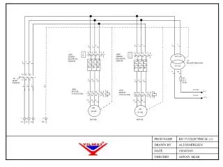
L1 L2 L3
6 7. 6 7 8. -KM1 MOTOR CONTACTOR. A1. 400 VAC. L1 L2 L3 13NO T1 T2 T3 14NO. TRANSFORMATOR. A2. 6 7 8. 24 VAC. 0 24. T1 T2 T3. L1 L2 L3 13 T1 T2 T3 14. 24 V FUSE. I 0. -SO MAIN SWITCH. -QM1

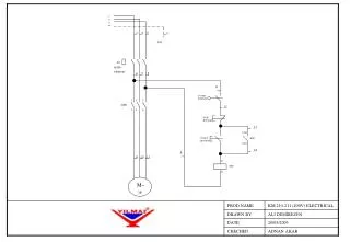
L1 L2 L3
E N D
Presentation Transcript
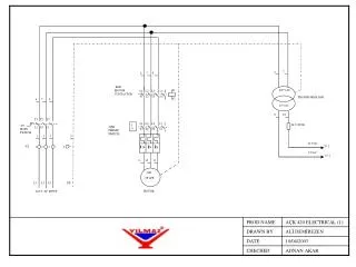
6 7 6 7 8 -KM1 MOTOR CONTACTOR A1 400 VAC L1 L2 L3 13NO T1 T2 T3 14NO TRANSFORMATOR A2 6 7 8 24 VAC 0 24 T1 T2 T3 L1 L2 L3 13 T1 T2 T3 14 24 V FUSE I 0 -SO MAIN SWITCH -QM1 TERMIC SWITCH L1 L2 L3 1 2 3 5 24 VAC S* 2 I > I> I> -X3 1 2 3 4 0 VAC S* 2 9 10 11 -M1 ~3P +PE L1 L2 L3 PE MOTOR 400 V AC INPUT
24 VAC \ S*1 24 -X1 1 FRONT COVER SWITCH 30 -X1 2 -X2 1 EMERGENCY STOP 31 MOTOR STOP 37 -X2 4 36 36 32 I START RIGHT I START LEFT -X2 2 MOTOR START 13NO -Y2 PRESSURE SWITCH -KM1 37 38 14NO 33 -X2 3 -X1 3 35 95 NC -QM1 TOP COVER SWITCH 96 NC -X2 5 34 33 34 -X1 4 39 X1 X2 -Y1 CUTTING VALVE A1 A2 MOTOR LAMP -KM1 A2 A1 0 0 0 0 VAC \ S*1
CLAMP CLAMP HIDRO-ÇEK PISTON HIDRO-CEK CUTTING PISTON -Y2 PRESSURE SWITCH -Y3 4 2 2 -Y1 5 3 1 3 1 LUBRICATOR AIR INPUT
CLAMP CLAMP HIDRO-CEK PISTON HIDRO-CEK CUTTING PISTON -Y2 SPREY PRESSURE SWITCH -Y3 4 2 2 WATER TANK -Y1 5 3 1 3 1 LUBRICATOR AIR INPUT