Download

1 / 37
380 likes | 482 Vues
Learn how Petri Nets transition to Event Graphs, understand basic elements, behavior, concurrency, and large model representations. Follow detailed mappings, state changes, and additional analytical methods for formalism and conditions. Explore implications and a fail-repair simulator for a comprehensive understanding.

E N D
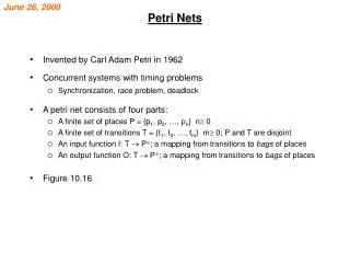
Alternative Implementations • Activity World View Petri Net Formalism: Simple fundamental elements and behavior Concurrent resource usage and contention • Event Scheduling View Event Graph Formalism: Simple fundamental element and behavior Concurrency and contention - large model representations
PN->EG MAPPING Transitions become timed edges Places become conditional edges
PN->EG Mapping: eg. G/G/s queue S PN: Q A T T s a
PN->EG Mapping: eg. G/G/s queue S PN: Q A T T s a EG: T T a s {A++, {A--} {Q--, {S++} Q++} S--}
PN->EG Mapping: eg. G/G/s queue S PN: Q A T T s a (A) EG: (S&Q) (S&Q) T T a s {A++, {A--} {Q--, {S++} Q++} S--}
PN->EG Mapping: eg. G/G/s queue Variable A is unnecessary! (A) (S&Q) (S&Q) T T a s {A++, {A--} {Q--, {S++} Q++} S--}
PN->EG Mapping: eg. G/G/s queue Empty Vertex is unnecessary! (S&Q) (S&Q) T T a s { Q++} {Q--, {S++} S--}
PN->EG Mapping: eg. G/G/s queue S&Q conditions redundant too... (S&Q) (S&Q) T T a s { Q++} {Q--, {S++} S--}
PN->EG Mapping: eg. G/G/s queue Result: a conventional G/G/s queue EG model (Q) T a (S) T s { Q++} {Q--, {S++} S--}
PNEG MAPPING P = set of Places, T = set of transitions in PN d(t) = delay time (RV) for transition tT {Ip(t),Op(t)}= Set of Input and Output Places for tT {It(p),Ot(p)}=Set of Input and Output Transitions for pP Step 0. pP: define an integer state variable, X(p). Step 1. tT: create an edge (O(t), D(t)) with delay d(t). Step 2. pP with unique (It(p),Ot(p)) pair: create the edge (D(It(p)),O(Ot(p))) with the condition that all pIp(Ot(p)) are marked. (For inhibitor arcs these places must not be marked.) Step 3. Add State changes: for O(t), decrement X(p) pIp(t); for D(t), increment X(p) pOp(t). Advanced homework: Confirm this or find a counter example.
Analytical Methods and Conditions • PNs Reachabilty, decidability, liveness, and deadlock • EGs State definition, event reduction, priorities, equivalence, boundary conditions, resource deadlock, MIP representations
COMMUNICATIONS BLOCKING (R1 needs empty buffer to Start) ... ... ... R1,R2 = Number of idle resources Q1,Q2 = Number of waiting jobs B = Number of empty buffer spaces ta,ts1,ts2 = Arrival and processing times
R1 R2 A Q1 Q2 W ts2 ta ts1 0 B COMMUNICATIONS BLOCKING: Petri Net Q1 = number of jobs waiting in queue 1 Q2 = number waiting in queue 2 R1 = idle resources for step 1 R2 = idle resources for step 2 B = available buffer slots
ts1 ts2 0 Each transition becomes a timed edge... R1 R2 A Q1 Q2 W ts2 ta ts1 0 B ta
(Q2&R2) (Q1&R1&B) ~ ~ ~ (Q1&R1&B) (Q2&R2) 0 ts2 ta ts1 ~ ~ ~ (W) ~ Next, each place becomes a conditional edge... (ALL input places marked is condition) R1 R2 A Q1 Q2 W ts2 ta ts1 0 B (A) (Q1&R1&B)
A Q1 Q2 W ts2 ta ts1 0 B Mapping Petri Net to Event Graph Finally, increment and decrement tokens as state changes R1 R2 ta (Q2&R2) (A) (Q1&R1&B) ~ ~ ~ (Q1&R1&B) (Q2&R2) 0 ts2 ta (W) ts1 ~ ~ ~ {A++, Q1++} {R2-- Q2--} {A--} {R1++, Q2++} {R2++} {Q1--, R1--. B--} {W++ B++} {W--} ~ (Q1&R1&B)
(Q2&R2) (A) (Q1&R1&B) ~ ~ ~ (Q1&R1&B) (Q2&R2) 0 ts2 ta (W) ts1 ~ ~ ~ {A++, Q1++} {R2-- Q2--} {A--} {R1++, Q2++} {R2++} {Q1--, R1--. B--} {W++ B++} {W--} ~ (Q1&R1&B) Final Event Graph: How can this be simplified? (ref: Seila, et. al. Text)
A Simplified Event Relationship Graph (Q2) (Q1&B) ~ ~ (R1&B) (R2) ta ts2 ts1 ~ ~ {R1++, Q2++} {R2-- Q2-- B++} {Q1--, R1--. B--} {Q1++} {R2++} ~ (Q1&R1)
Implications • PN analysis of Event Graphs State reachability Liveness Deadlock • EG analysis of Petri Nets State space Model reduction Equivalence Boundary Conditions Resource Deadlock
Fail-Repair PN: EG: D a C B A t 0 t f r (D&B) t t f 0 (C) r (D&B) (A&!B)
PN->EG Mapping Transformed EG Failure-Repair Model (A&&!B) (B&&D) / / / / (B&&D) (C) B-- A++ / / / / 0 A-- D++ C-- C++ B++ D-- / / (A&&!B) D=3
PN->EG Mapping Reduced EG Failure-Repair Model t f t r Fail F i x {N++} {N- -}
EG -> PN Mapping • Conditions: Need to have non-negative, integral state changes Test only for non-negativity of integers Needs to “edge bi-partite” pure-timed and pure- conditional edges alternate Single state change at each vertex - upstream of timed decrement, downstream of timed increment • Expansion Algorithm of Yucesan and Schruben Add conditions upstream when breaking up a self-scheduling edge (Yucesan and Schruben)
EG -> PN Mapping 1. Split all self-scheduling edges (add conditions upstream of new vertex) 2. Add void edges (either conditional or timed but not both) to make graph “edge-bipartite” (expansion rules) 3. Timed edges become transitions and conditional edges become places
EG -> PN Mapping EG->PN not possible ( C L K < 1 0 0 ) ( Q > 0 ) t a ( S > 0 ) t s ENTER START LEAVE { S = 1 } { Q = Q + 1 } { S = 0 , Q = Q - 1 }
EG -> PN Mapping (Q) (S) t s START QUEUE FINISH t a {Q=Q - 1, {S=S+1} {Q=Q+1} S=S - 1}
EG -> PN Mapping (Q) (S) t s START QUEUE FINISH t a {Q=Q - 1, {S=S+1} {Q=Q+1} (Q) S=S - 1} t a (S) t s ? START QUEUE FINISH “Edge Bipartite”
EG -> PN Mapping (Q) (S) t s START QUEUE FINISH t a {Q=Q - 1, {S=S+1} {Q=Q+1} (Q) S=S - 1} t a (S) t s ? START QUEUE FINISH Timed Edges become Transitions t t s a
EG -> PN Mapping (Q) (S) t s START QUEUE FINISH t a {Q=Q - 1, {S=S+1} {Q=Q+1} (Q) S=S - 1} t a (S) t s ? START QUEUE FINISH ??? Conditional Edges become PN places t t s a
EG -> PN Mapping (Q) (S) t s START QUEUE FINISH t a {Q=Q - 1, {S=S+1} {Q=Q+1} (Q) S=S - 1} t a (S) t s ? START QUEUE FINISH S State changes on conditional edges determine labels ? Q t t s a
COMMUNICATIONS BLOCKING: Edges Mapped from Petri Net (i) ~ (i) (ii) Run Enter Start1 ts1 End1 Start2 ~ ~ ta ts2 ~ (ii) ~ (i) End2 Conditions to Start “Activities”: (i )= (R1&B&Q1) (ii) = (R2&Q2)
COMMUNICATIONS BLOCKING: State Changes {R1--, B--, Q1--} {R1=1, R2=1, B=4} {R1++, Q2++} {R2--, Q2--} {Q1--} Run Enter Start1 End1 Start2 End2 R1,R2 = Number of idle resources Q1,Q2 = Number of waiting jobs B = Number of empty buffer spaces {R2++, B++}
COMMUNICATIONS BLOCKING: Final EGM Model {R1--, B--, Q1--} {R1=1, R2=1, B=4} {R1++, Q2++} {R2--, Q2--} (R1&B&Q1) {Q1--} ~ Run Enter Start1 End1 Start2 ts1 (R2&Q2) ~ ~ ta (R1&B&Q1) ts2 ~ ~ (R2&Q2) (R1&B&Q1) End2 R1,R2 = Number of idle resources Q1,Q2 = Number of waiting jobs B = Number of empty buffer spaces {R2++, B++}
DELAY SEIZE RELEASE Queue Idle Resources Using Activity Scanning to Develop Process Models “Color” tokens that represent Transient Entities - - track these tokens’ paths. Parse Activities into “SEIZE”, “DELAY” and “RELEASE” Blocks.
Process -> EG Mapping Process World View: • Automated SLAM to Event Graphs (Woodward and Mackulak, ASU) Resource deadlock detection • SIMAN to Event Graphs (Barton and Gonzalez, PSU) Premature run termination