Head loss in a pipe—using the Darcy-Weisbach Equation
360 likes | 3.43k Vues
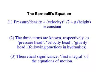
On noting that. We can write. In this case we can calculate the resistance r for a given pipe and use the form. to analyses flow in pipe networks. Head loss in a pipe—using the Darcy-Weisbach Equation.

Head loss in a pipe—using the Darcy-Weisbach Equation
E N D
Presentation Transcript
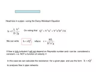
On noting that We can write In this case we can calculate the resistance r for a given pipe and use the form to analyses flow in pipe networks Head loss in a pipe—using the Darcy-Weisbach Equation If flow is fully turbulent f will not depend on Reynolds number and r can be considered a constant—i.e. NOT a function of velocity V
Flow in a Parallel Pipe System So for loop 1 we have For loop 2 Consider flow from A to B through the three pipes in the directions shown. If the flow upstream of A is Q m3/s how is it split between pipes 1, 2 and 3. • The diagram has Two NODES A and B • (points where pipe join) • And Two LOOPS • From A along pipe 1 to B • and back along pipe 2 to A • From A along pipe 2 to B • and back along pipe 3 to A 1 A B 2 3 Head loss will increase as we move in direction of flow and decrease as we move against flow There can be NO net change in head around a closed loop. (1) (2) (3) Continuity IF Q is known we can solve the three equations (Using SOLVER in EXCELL) to obtain Values for the Qi Download excel file “parbal.xls” in notes section
We can extend the ideas to general Pipe Networks exercise 1 in the pipe network lab 4 NODES A, B, C, D 5 Pipes 2 Loops For given Q inputs at A, B, C and D and r’s determine Pipe discharges Loop 1:R1*QQ1*ABS (QQ1) +RR4*QQ4*ABS (QQ4) + RR5*QQ5*ABS (QQ5) = 0 Loop 2: -RR2*QQ2*ABS(QQ2) - RR3*QQ3*ABS(QQ3) + RR4*QQ4*ABS(QQ4) = 0 Balance Node A: QQA + QQ5 – QQ1 = 0 Balance Node B: QQ1 – QQ2 – QQB – QQ4 = 0 Balance Node C: QQ2 – QQ3 – QQC = 0 Balance Node D: QQ3 + QQ4 + QQ5 – QQD = 0 Overall Balance: QQA – QQB – QQC – QQD = 0 More equations than we need—But SOLVER can handle them Note if you “Guess” a wrong direction fro flow the discharge value will be negative
El. 25 m El. 25 m El. 20 m El. 20 m L L 3 3 L L El. 0 El. 0 2 2 L L P P 1 1 Pipe systems with reservoirs and pumps One Node And ??? Loops Create “pseudo loops” with zero flows (Q = 0) between reservoirs surfaces Then head-loss loop equations are Note: directions around loops There is a positive head loss when we move through a pump opposite to flow direction Continuity
El. 25 m El. 20 m L 3 L El. 0 2 L P 1 hp h Q More on the pump The efficiency of the pump is also a function of Q It will be zero at “shutoff” and free-delivery and attaint a maximum < 100% for It is important to choose a pump That is efficient for required Q The head provided by the pump is a function of the discharge Q through it The shutoff head the maximum head that can be provided—the pump can lift water to this height BUT water can not flow (Q = 0) The free-delivery This is the maximum flow through the pump. It can only be achieved if no pipe is attached to the pump ( hP = 0).