Download
1 / 9
140 likes | 382 Vues
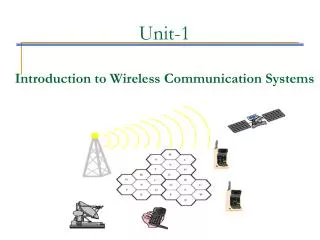
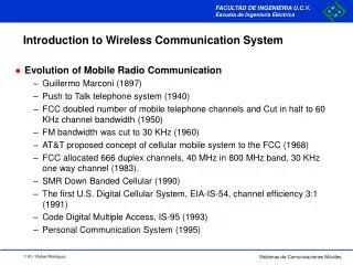
Introduction to Wireless Communication System. Evolution of Mobile Radio Communication Guillermo Marconi (1897) Push to Talk telephone system (1940) FCC doubled number of mobile telephone channels and Cut in half to 60 KHz channel bandwidth (1950) FM bandwidth was cut to 30 KHz (1960)

E N D
Introduction to Wireless Communication System • Evolution of Mobile Radio Communication • Guillermo Marconi (1897) • Push to Talk telephone system (1940) • FCC doubled number of mobile telephone channels and Cut in half to 60 KHz channel bandwidth (1950) • FM bandwidth was cut to 30 KHz (1960) • AT&T proposed concept of cellular mobile system to the FCC (1968) • FCC allocated 666 duplex channels, 40 MHz in 800 MHz band, 30 KHz one way channel (1983). • SMR Down Banded Cellular (1990) • The first U.S. Digital Cellular System, EIA-IS-54, channel efficiency 3:1 (1991) • Code Digital Multiple Access, IS-95 (1993) • Personal Communication System (1995)
Introduction to Wireless Communication System • Growing • Techno-politics are fundamental driver in the evolution of new technology and services • Competitiveness in the rapid changing field of Wireless Personal Communication • Fastest Growth due wide spread deployment • Growth rates well in excess of 50% per year • First couple of decades of the 21th century, there will be an equal number of wireless and conventional wireline customer in the world
Introduction to Mobile Communication System • Use of higher frequencies • Urban area coverage • Mobile system signals suffer big variations • Reuse of frequencies without interfering with each other • Random phase Each component plane wave has associated with it, depending on the: • Mobile speed • Carrier frequency • Incidence angle
Factors affecting transmission • Free Space path losses The receive radiated power decrease 6 dB for each doubling of the frequency • Propagation over a plane earth Bullington simplified Norton’s solution into a set of waves: • Direct wave • Reflected wave • Surface wave • Rough Surface criterion Due surface irregularities • Refraction and Equivalent earth’s radius The refraction index of the atmosphere is not constant • Effects of rain and atmosphere Losses depend upon the frequency and upon the amounts of moisture in the path
Radio Propagation effects • Path Loss • Free Space Path Loss • Mobile Radio Environment Path Loss (OKUMURA) • Fading • Long term Fading Terrain configuration and human-made environment, log-normal variation for signal strength measured over 40 • Short term Fading (Rayleigh fading) Multiple signals interferences • Time delay Spread Two ray multipath delay • In-building, t < 0.1s • Open area , t < 0.2s • Suburban area , t < 0.5s • Urban area , t < 3s
d3 d1 d2 h2 h1 H Ant1 Ant2 d1 d2 d1<<d2 Factors affecting transmission • Transmission over smooth spherical earth Predict the signal attenuation over transhorizon path • Knife edge diffraction
Signal Prediction Models • OKUMURA • Signal Prediction Models for Urban areas (1968) • Relative to free space in an urban quasi-smooth environment • Reference curves were developed from extensive measurements using vertical omni antennas • Frequencies range 150 MHz to 1920 MHz • Distances range 1 Kmts to 100 Kmts • Base Station antenna heights 30 mts to 1000 mts • Simplest and best in terms of accuracy in path loss prediction for Cellular and LMR • Slow response to rapid change in the terrain (for urban areas) L50(dB) = LF + Amu(f,d) - G(hte) - G(hre) - GAREA
Signal Prediction Models • BULLINGTON • Published by Keneth Bullington 1947 • Modified basic free space and plane earth model by including diffraction losses. • Diffraction losses • Over smooth spherical earth • Curvature of the earth • Distance to horizon • Knife-edge • Signal Prediction Models for any areas • Response to rapid change in the terrain