Download
1 / 25
250 likes | 397 Vues
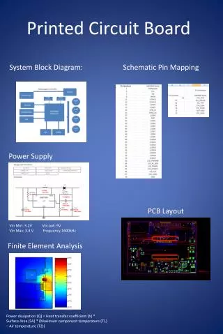
Environmental Simulation of Circuit Board Epoxy. Group Members Greg Kurtz Brad Walsh Brad Grimmel Jeff Baudek. Project Overview. Lockheed/Martin is having a problem with cracking in circuit boards and circuit board epoxy Project involves Repairing an environmental chamber

E N D
Environmental Simulation of Circuit Board Epoxy Group Members Greg Kurtz Brad Walsh Brad Grimmel Jeff Baudek
Project Overview • Lockheed/Martin is having a problem with cracking in circuit boards and circuit board epoxy • Project involves • Repairing an environmental chamber • Duplicating the cracking through physical testing • Using FEA/FEM to model circuit boards • Proposing a solution
Environmental Chamber • Must cycle temperature from –50°C to 80°C in one hour
Replaced Blower motor Selected and Purchased new controller Rewired LN2 solenoid and cables between chamber and controller Made new wiring diagrams for operator references Had new 208V 40A power outlet installed in NHMFL Repairs Made to Chamber
Chamber was cycled through maximum range of –73°C to 316°C Chamber is capable of completing diurnal cycle from –50°C to 80°C in less than one hour Testing of Repaired Chamber
Purpose of testing was to simulate the effect of the standard military diurnal cycle on a UR-329 encapsulated circuit board Circuit Board Testing
Preparation Procedure • Heat mold to 100°C and apply releasing agent • Mix resin and hardener and insert into vacuum chamber (samples were also prepared without vacuum) • Curing period (either normal or accelerated cure)
Physical Testing • Samples were then cycled between –50 deg C and 80 deg C each hour • Samples were checked approximately every 25 cycles • Samples were exposed to approximately 550 cycles during testing
Results of Testing • Cracking in epoxy
Results of Testing (Cont’d) • Cracking in circuit board
Finite Element Analysis (FEA) • 2-D and 3-D models made using FEA programs Ansys and Algor • Assumptions • Uniform Temperature Distribution • Constraint of zero displacement at two corners • Constant Material Properties
Epoxy Circuit Board Circuit Board Epoxy Fixed Points Fixed Points FEA Schematics 2-D 3-D
Results of FEA • 2-D Ansys model showed stresses that were below the yield point of the circuit board • 3-D Ansys model was inaccurate due to constraints • 3-D Algor model showed that the stress present in the circuit board was below the yield point
Fe Fe Fb Fb M M Thermal Stress Calculations • Axial and Bending Stress due to temperature variations in the circuit board and epoxy were done to supplement the FEA
Assumed: Constant value of E and CTE Epoxy delaminated from the circuit board Uniform temperature distribution Model Setup Basic Equations: DL = LoaDT
Results of Calculations • Calculated Axial stresses were below the yield stress of the ceramic throughout the entire temperature range • Calculations determined that with a constant CTE of 191.7*10-6/°C an Elastic Modulus of 4230 psi for the epoxy is needed to crack the circuit board due to bending stress which occurs within the diurnal cycle specified by Lockheed/Martin for testing
Summary • Repair of Environmental Chamber • Recreation of circuit board and epoxy cracking through physical testing and observed using SEM • FEA was completed • Thermal stress calculations revealed that circuit board should crack
Recommendations • Use epoxy with • A modulus of elasticity with a lower glass transition temperature • A decreasing coefficient of thermal expansion with decreasing temperature • Further investigation of: • Fatigue properties of circuit board • Adhesive properties of the epoxy • Examine use of different epoxy fillers