Download
1 / 18
440 likes | 1.74k Vues
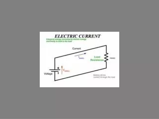
Buffer amplifier. Sallen and Key Two Pole Filter. But. Apply Kirchoff’s current law to v 1 node:. Substituting,. Two-Pole Low-Pass Filter. Two-Pole High-Pass Filter. So,. Eg. Two-Pole Example. Design a second order normalised Butterworth low pass filter. Higher Order Filters.

E N D
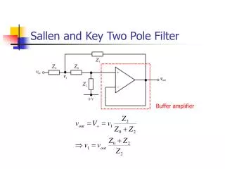
Buffer amplifier Sallen and Key Two Pole Filter
But Apply Kirchoff’s current law to v1 node:
So, Eg. Two-Pole Example Design a second order normalised Butterworth low pass filter.
Higher Order Filters • Using a single op-amp the highest order practical filter design is two. • For higher order filters, more than one op-amp is needed. • Simplest design technique is cascade synthesis or synthesis by sections.
Synthesis by Sections • When two (or more) filters are cascaded in series, the total transfer function is the product of the individual transfer functions. • HTOT(s) = H1(s) H2(s) • The required transfer function must be factorised into second order sections. H1(s) H2(s) VIN(s) VIN(s)H1(s) VIN(s)H1(s) H2(s)
Factorising the Transfer Function • Filter design techniques usually generate the positions of the poles (and zeros) of the transfer function. • Grouping complex conjugate pairs together is essential for physically realisable sections. • If the required filter order is odd, a single pole will be left over. This is realised by a first order section.
Transfer function is, therefore: Fourth Order Example The poles of a normalised fourth order low pass Butterworth filter are:
Third Order Example The poles of a normalised third order low pass Bessel filter are: Transfer function is, therefore:
Ordering the Sections • In theory, using ideal op-amps, it doesn’t matter which section is first or second. • In practice, the decision is based on considerations of: • Saturation Levels • Noise Figure From fourth order example:
Second Order Frequency Response • If the damping ratio, z, is less than 1/Ö2, the peak gain is greater than one. • This means that the maximum input level is reduced, to avoid op-amp saturation. 10 z=0.2 0.707 1 0.5 1 Gain z=2 0.1 0.01 1 0.1 10 Frequency [rad/s]
H1(s) H2(s) H2(s) H1(s) At w = 1 rad/s,
Section Ordering • To get the highest maximum input signal range. • Sections with the largest damping ratio (lowest Q) should come first. • Resonant sections with low damping ratios come last, possibly susceptible to noise. • To get the lowest output noise. • Highest gain sections (i.e. most resonant) should come first. • Subsequent sections attenuate noise. • What’s the best order ? • It depends.
Summary • The Sallen and Key configuration realises a two-pole filter section using a single op-amp. • Synthesis by sections creates higher order filters by cascading first and second order sections. • Under ideal assumptions, the order of the sections is irrelevant. • Practically, dynamic range considerations decide the order of the sections.