Op Amp compensation
840 likes | 1.44k Vues
Op Amp compensation. The design process involves two distinct activities: Architecture Design Find an architecture already available and adapt it to present requirements Create a new architecture that can meet requirements Component Design Determine transistor sizes

Op Amp compensation
E N D
Presentation Transcript
Op Amp compensation The design process involves two distinct activities: • Architecture Design • Find an architecture already available and adapt it to present requirements • Create a new architecture that can meet requirements • Component Design • Determine transistor sizes • Determine biasing voltages/currents • Design compensation network
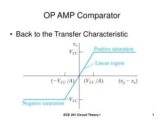
All op amps are used as feedback amplifier: If not compensated well, closed-loop can be oscillatory or unstable. Damping ratio z ≈ phase margin PM / 100 Value of z: 1 0.7 0.6 0.5 0.4 0.3 Overshoot: 0 5% 9.6% 16% 25% 37% PM in deg: 67 61 53 44 35 PM+Mp: 72 71 69 69 72 PM+Mp ≈ 70
UGF: frequency at which gain = 1 or 0 dB PM: phase margin = how much the phase is above critical (-180o) at UGF Closed-loop is unstable if PM < 0 UGF This is the loop-return gain when used in closed-loop. Only in buffer connection this is equal to O.L. gain. PM
UGF p1 p2
UGF GM p1 p2 z1 PM
Types of Compensation • Miller - Use of a capacitor feeding back around a high-gain, inverting stage. • Miller capacitor only • Miller capacitor with an unity-gain buffer to block the forward path through the compensation capacitor. Can eliminate the RHP zero. • Miller with a nulling resistor. Similar to Miller but with an added series resistance to gain control over the RHP zero. • Self compensating - Load capacitor compensates the op amp (single stage). • Feed forward - Bypassing a positive gain amplifier resulting in phase lead. Gain can be less than unity.
Miller Effect Two stage Miller compensation v2 v1 i v2= AVv1 v1 i= v1/Z1 i= -v2/Z2 i = (v1-v2)/Zf = v1(1-AV)/Zf = v1/{Zf /(1-AV)} = - v2(1-1/AV)/Zf = - v2/{Zf /(1-1/AV)} Caution: This is only valid when Av independent of Zf. This is the case at low freq.
Nested Miller Compensation (NMC), • Reverse Nested Miller Compensation (RNMC), • Multipath Nested Miller Compensation (MNMC), • Nested Gm-Cc Compensation (NGCC)
Active feedback frequency compensation (AFFC), • Transconductance with capacitance feedback frequency compensation (TCFC)
Single ended and differential have very similar Compensation needs Not quite VBP VBP I2 I1 Vo1 I2 Vo1 Vi Vo Vi- Vo Vi+ VBN I1 VBN
VBP VBP Vo1 CC CC Vi Vo Vi+ Vo+ Vo- Vi- Vb1 Vb1 VBN
If the first stage is cascoded, the analysis stays similar VBP VBP VBPc Vo1 CC CC VBNc Vo Vo+ Vo- Vi Vi- Vi+ Vb1 Vb1 VBN Composite MOST with very large ro
VDD Folded cascode same thing, except gm is from a different pair IN- IN+ CC CC Vo+ Vo-
Generic representative: VBP Vo1 Vi Vo Vb1
CL In buffer configuration: Vo1 Vi- =Vo Vid = Vi+ - Vi- =Vin – Vi- =Vin – Vo Vo=Avd(s)Vid b=1 Vi- Vi+ Vo Vin Vid Vo Vin(s) + Ao(s) -
Stability simulation • Perform “open loop” frequency response • Check PM at UGF • Use PM to predict overshoot in closed-loop small signal step response • Need to include input impedance at vi- in total output impedance at vo.
CL For closed-loop evaluation: Apply source at Vi+. Vo1 Vi- Vi+ Vo Vin Vid Vo Vin(s) + Ao(s) -
CL For open-loop evaluation: Insert source at Vi-. Vo1 Vi- =Vo + Vin Vid = Vi+–Vi- = – Vi- = – Vin – Vo Vo=Avd(s)Vid b=1 Vi- Vi+ Vo + - Vin Vid Vo -Vin(s) + Ao(s) -
CL What about R-feedback? Vid = -Vi-has two components: When Vin=0, When Vo=0 Vo1 Vin Vi- Vi+ Vo Ri Rf -Vi- Vin(s) Vo + Gin(s) Ao(s) - b(s)
CL Open loop simulation incorporating feedback loading VoQ = Vicm Vo1 Rf Vi- Vi+ Vo V’o Ri Obtain freq resp from Vid to V’o
Alternative simulation (more reliable) CL Vo1 Vi- Vi+ Vo Ri Vin Vid = Vi+ - Vi- =Vin – Vi- Vi- =b(s)Vo Vo=Avd(s)Vid Rf Vi- Vin Vo Vid
V’o VBP Ri VBPc CC CC VBNc Rf Vo+ Vo- Vi- Vi+ Vb1 VBN Ri
VBP VBPc Rf CC CC VBNc Vo- Vi+ Vi- Vo+ Rf Vb1 Ri VBN Ri Vid -Vid Vicm – VocmRef – s.s. vid/2 VocmRef Vicm – VocmRef + s.s. vid/2
Generic representative: VBP Yc M4 Vo1 M6 vi vo Vi -gm2 -gm6 M2 Vo Vb1 M7 Zo Zo1 sCgd2 sCgd6
Yc+sCgd6 vi Io1 vo1 Io vo -gm6 Zo1 Zo sCgd2-gm2 Yc+sCgd6
VBP I2 I1 Vo1 Yc+sCgd6 Vi- Vo Vi+ sCgd2-gm2 Vid Vi+ Io1 vo1 Io vo 0.5 VBN -gm6 Zo1 Zo Vi- -0.5 Vm Yc+sCgd6 Im
HW: • Finish the above signal flow graph • Re-arrange it and show that the graph on p28 still applies if sCgd2-gm2 is replaced by (sCgd2-gm2)*G(s) with proper G(s) • Obtain the new TF by modifying the TF on p29
DC gain of first stage: AV1 = -gm2/go1 = -gm2ro1 DC gain of second stage: AV2 = -gm6/go = -gm6ro Total DC gain: gm2gm6 AV = = gm2gm6ro1ro go1go BW = |p1| go1go/gm6CC GBW = gm2/CC
gm6/(CL+C1) f (I6) A0 z1 ≈ gm6/(CC+Cgd6) w1 w2 z2 ≈ gm2/Cgd2 0dB -90o No PM -180o
gm6/(CL+C1) f (I6) A0 3 1 2 4 z1 ≈ gm6/Cgd6 Cc z2 ≈ gm2/Cgd2 w1 w2 z1 ≈ gm6/Cc 4 3 1 2 -90 3 2 4 1 No PM -180
gm6/(CL+C1) f (I6) A0 gm1/CC w2 z1 ≈ gm6/CC w1 -90 PM -180
It is easy to see: PM ≈ 90o – tan-1(UGF/w2) – tan-1(UGF/z1) To have sufficient PM, need UGF < w2 and UGF << z1 In such case, UGF ≈ GB ≈ gm1/CC = z1 * gm1/gm6. GB < w2 GB << z1 Hence, need: PM requirement decides how much lower: PM ≈ 90o – tan-1(GB/w2) – tan-1(GB/z1)
Possible design steps for max GB • For a given CL and Itot • Assume a current share ratio q, i.e. • I6+I5 = Itot, I5 = qI6 , I1 = I2 = I5/2 • Size W6, L6 to achieve max gm6/(CL+Cgs6) which is > w2 • C1 W6*L6, gm6 (W6/L6)0.5 • Size W1, L1 so that gm1≈ 0.1gm6 • this make z1 ≈ 10*GB • Select CC to achieve required PM • by making gm1/CC < 0.5 w2 • Check slew rate: SR = I5/CC • Size M5, M7, M3/4 for current ratio, ICMR, etc
Comment • If we run the same total current Itot through a single stage common source amplifier made of M6 and M7 • Single pole go/CL • Gain gm6/go • Single stage amp GB = gm6/C’L >gm6/(C’L+C1) > w2 > gm1/CC = GB of two stage amp • Two stage amp achieves higher gain but speed is much slower! • Can the single stage speed be recovered?
Other considerations • Output slew rate: SR = min{I5/CC, I6/Co} • Output swing range (saturation operation): VSS+Vdssat7 to VDD – Vdssat6 • Min ICM: VSS + Vdssat5 + VTN + Von1 • Max ICM: VDD - |VTP| - Von3 + VTN • Mirror node approx. pole/zero cancellation • Closed-loop pole stuck nearby • z3 –gm3/Cgs3, p3 z3/2 • Can cause slow settling if pole freq is too low
Eliminating RHP Zero at gm6/CC VBP Vo1 Vi Vo Vb1 C1 Cgs6 + Cdb2 +Cdb4 C’L CL + Cdb6 +Cdb7
For the zero at M6 and CC, it becomes z1 = gm6/[CC(1-gm6Rz)] So, if Rz = 1/gm6, z1 → Notice that Rz is referenced with respect to 1/gm6. Since absolute values of both R and gm can vary significantly, but relative match is more precise, Rz is usually implemented as a triode transistor.
Realization of Rz: Mz has same type and Vod as M6, gdsz = gdoz = gm6 * size ratio vb
VDD M8 M9 M6, M8, M9 have same W and L, but their multiplier ratio = current ratio
Another choice of Rz, as in our book, is to make z1 cancel p2: z1=gm6/CC(1-gm6Rz) ≈ - gm6/(CL+C1) CC+CL+C1 Rz = gm6CC CL+C1 1 (1+ ) = CC gm6 CL+C1 (1+ ) = gm6 Or: gdoz * CC
Let ID8 = aID6, size M6 and M8 so that VSG6 = VSG8 Then VSGz=VSG9 Assume Mz in triode gdoz = bz(VSGz – |VT|) = bz((VSG9 – |VT|) = bz(VSG8 – |VT|) = bz(VSG6 – |VT|) = (bz/b6)gm6 = (Sz/S6)gm6 Hence need: Sz/S6 =CC/(CC+CL+C1)