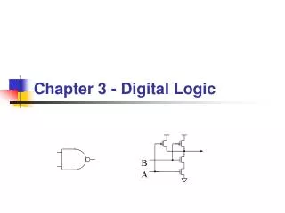
Chapter 3 Digital Logic Structures
Chapter 3 Digital Logic Structures. Basic Logic Gates. Basic Relations of Boolean Algebra. x + 0 = x x + 1 = 1 x + x = x x + x ’ = 1 x + y = y + x (Commutative) x + (y+z) = (x+y)+z (Associative) x (y+z ’ ) = x y + x z (Distributive) (x+y) ’ = x ’ y ’ (DeMorgan) (x ’ ) ’ = x.


Chapter 3 Digital Logic Structures
E N D
Presentation Transcript
Basic Relations of Boolean Algebra • x + 0 = x • x + 1 = 1 • x + x = x • x + x’ = 1 • x + y = y + x (Commutative) • x + (y+z) = (x+y)+z (Associative) • x(y+z’) = xy + xz (Distributive) • (x+y)’ = x’ y’ (DeMorgan) • (x’)’ = x • x0 = 0 • x1 = x • xx = x • xx’ = 0 • xy = yx (Commutative) • x(yz) = (xy)z (Associative) • x+yz = (x+y)(x+z) (Distributive) • (xy)’ = x’+y’(DeMorgan) + = OR = AND ‘ = NOT
= = DeMorgan’s Law • not(A and B) = (not A) or (not B) • not(A or B) = (not A) and (not B)
More than 2 Inputs? • AND/OR can take any number of inputs. • AND = 1 if all inputs are 1. • OR = 1 if any input is 1. • Similar for NAND/NOR. • Can implement with multiple two-input gates,or with single CMOS circuit.
Summary • MOS transistors are used as switches to implementlogic functions. • n-type: connect to GND, turn on (with 1) to pull down to 0 • p-type: connect to +2.9V, turn on (with 0) to pull up to 1 • Basic gates: NOT, NOR, NAND • Logic functions are usually expressed with AND, OR, and NOT • DeMorgan's Law • Convert AND to OR (and vice versa) by inverting inputs and output
Building Functions from Logic Gates • Combinational Logic Circuit • output depends only on the current inputs • stateless • Sequential Logic Circuit • output depends on the sequence of inputs (past and present) • stores information (state) from past inputs • We'll first look at some useful combinational circuits,then show how to use sequential circuits to store information.
Decoder • n inputs, 2n outputs • exactly one output is 1 for each possible input pattern 2-bit decoder
Multiplexer (MUX) • n-bit selector and 2n inputs, one output • output equals one of the inputs, depending on selector 4-to-1 MUX
A B C D S0 S1 A B C D Out S[1:0] Out Mux (cont.) • In general, a MUX has • 2n data inputs • n select (or control) lines • and 1 output. • It behaves like a channel selector. A 4-to-1 MUX: Out takes the value of A,B, C or D depending on the value of S (00, 01, 10, 11)
Adder • Half Adder • 2 inputs • 2 outputs: sum and carry • Full Adder • performs the addition in column i • 3 inputs: ai, bi and ci • 2 outputs: si and ci+1 • ci is the carry in from bit position i-1 • ci+1 is the carry out to bit position i+1 Half-adder truth table
Full Adder • Add two bits and carry-in,produce one-bit sum and carry-out.
Full Adder (cont) where - verify that this corresponds to the gate-level implementation.
Four-bit Adder 1010 Cin 0101 A + 1101 B 10010 S
Logical Completeness • Can implement ANY truth table with AND, OR, NOT. 1. AND combinations that yield a "1" in the truth table. 2. OR the resultsof the AND gates.