Download
1 / 17
170 likes | 198 Vues
This presentation delves into the absolute photon calibration methods of the Zeiss Observer Z1 Microscope, focusing on the use of standard lamps, Plank's curve, and measurement techniques for accurate photon detection. The design details, system alignment steps, measurements, solid angle calculations, and area of filament magnification are thoroughly discussed to ensure precise calibration. The number of photons collected, theoretical calculations, and references for further study are also provided.

E N D
Absolute Photon Calibration of Zeiss Observer Z1 Microscope Shawn Miller Department of Optical Sciences University of Arizona, Tucson, AZ 85721 Optics 521 Presentation December 8, 2008
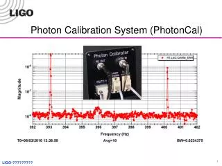
Absolute Photon Calibration • Detectors give relative light intensity values. • Must provide reference to actual photon numbers for the detector’s value. • “Standard” lamp which has been calibrated to national standards.
Standard Lamp • Tungsten ribbon filament lamp. • Temperature is calibrated for several currents. • Stable high current power supply. • High wattage resistor. • Photon emission is given by Plank’s curve.
Lamp Calibration Form • Calibrated at hottest (most central) area of the filament. • Calibrated in the vertical position. • 20% variation in lamp emission. • Area of filament viewed by optical setup is very important.
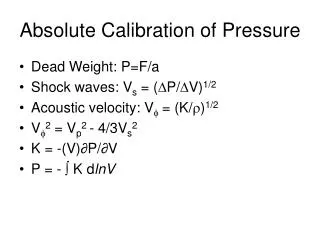
Plank’s Curve • Absolute temperature. • 1/ Ta = 1/ Tb + (λ/C2)*[ln(ε(λ)) + ln(τ(λ))] • Ta = Absolute temperature • Tb = Brightness temperature • λ = Wavelength of radiation • C2 = Plank’s second constant = hc/Kb • ε(λ) = Emissivity at emitting wavelength • τ(λ) = Transmission of pyrex envelope. • L(λ) = ε(λ,Ta)*τ(λ)*[2hc2/λ5] / (ehc/λKbTa – 1). • Integrate over wavelength region being observed.
Collecting the Lamp’s Light • Φ = ∫L(λ)dλ*A*Ω. • Φ = Flux of light. • Watts, or ergs/second. • ∫L(λ)dλ = Radiance. • W/m2*Sr • A = Area of filament. • m2 • Ω = Solid Angle. • Sr
Zeiss Observer Z1 Microscope • EMCCD camera. • Three objectives. • 8 wavelength filters. • 6 gain settings. • Detector’s response is different for each setting.
A Simple Design • Small central area of the filament imaged onto the focal plane the objective lens. • Lamp stand, two lenses, mirror, and stop.
Design Details • First lens mount. • Barrel mount. • Axially adjustable by threading the mount into the lamp housing. • About one focal length from filament. • Off Axis alignment is a one time adjustment of setscrews.
Design Details • Mirror mount / aperture stop. • Adjustable kinematic mirror mounted above aperture at 45° • One time adjustable height. • Base for aperture slide. • Connection to microscope.
Design Details • Second lens mount. • Adjustable height. • One time off axis adjustment. • Fixed in place with epoxy. • Microscope’s stage acts as fine system adjustment when removing and replacing system.
System Alignment • Set lamp height. • Adjust first lens. • Adjust mirror height. • Set mirror alignment. • Center second lens. • Epoxy in place. • Adjust second lens height.
Measurements • Calculate first lens to filament distance. (z1) • Measure width of filament spot on wall and distance to wall. • z1 = (-Wf/Ww)*(DL1w). • Aperture radius measured with 10x objective. (Rs) • Distance from first lens to stop and to the second lens measured with caliper. (DL1S, DL1L2)
Solid Angle • 1/z1’ = 1/z1 + 1/f1. • RL1 = Rs + [Rs/(z1’–(DL1s))]*(DL1s). • RL1 = Radius of light spot on first lens. • Ω = π RL12/z12
Area of Filament / Magnification • Radius of the filament being imaged onto the objective lens focal plane. (Rfo) • Rfo = z1*(Rs/(DL1s). • Radius of the filament image in the objective lens focal plane. (Ro) • m = -Ro / Rfo. • 100x and 40x objective. • Wf = Wfov / m. • Af = (Wfov / m)2. • Area of the filament viewed by the microscope.
Number of Photons • Φ = L*A*Ω*TL*Rm. • TL = Transmission of lenses. • Rm = Reflectivity of mirror. • Theoretical # Photons = (Φ*t*λ) / (h*c). • t = Exposure time. • λ = Central wavelength. • h = Plank’s constant. • c = Speed of light. • Calibration factor = #Pt / Detector reading.
References • Kowalski, Brian. Absolute calibration of a spectrometer through the ultraviolet. Department of Physics Thesis, 1993. • Bickel, William. Absolute intensity calibration of a spectrometer using a blackbody radiation source. Short paper, September 2001. • Merchant, John. Blackbody calibration sources function as standards. Laser focus world, April 1995. • Stair, Ralph. Standard of Spectral Radiance for the Region of 0.25 to 2.6 microns. Journal of Research of the National Bureau of Standards, Physics and Chemistry Vol. 64A, No.4, July-August 1960. • G.A.W., Rutgers. “Relation between brightness, temperature, true temperature and color temperature of tungsten. Luminance of tungsten.”