Download
1 / 23
230 likes | 245 Vues
Implementing a synchronous 16-channel acquisition system for the two-bar test using WaveCatcher V5 boards and USB connectivity. The system ensures precise time tagging and synchronization for event recording and data readout. Challenges and solutions throughout the setup process are discussed.

E N D
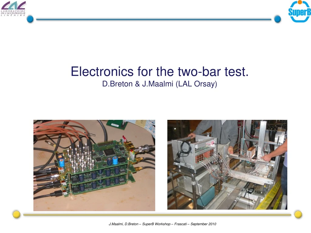
Electronics for the two-bar test.D.Breton & J.Maalmi (LAL Orsay)
For the two-bar test at SLAC, wehad to build a synchronoussixteenchannel acquisition system based on 8 two-channelWaveCatcher V5 boards: The system has to workwith a commonsynchronousclock There wetakebenefit of the externalclock input of the WaveCatcher V5 It is self-triggered but italso has to besynchronizedwith the rest of the CRT True not only for running acquisition but also for time tagging of events Like the WaveCatcher, data acquisition isbased on 480Mbits/s USB. Introduction
Experimental setup Faraday cage 16 SMA connectors To amplifiers PM-side harness Patch panel Trigger for the electronics crate (QTZ3)
PM-sideharness All the lines between the MCP anodes and the cable inputs are 14.7mm long
36dB Amp 36dB Amp 36dB Amp 36dB Amp CH0 CH0 CH0 CH0 CH0 CH0 CH0 CH0 CH1 CH1 CH1 CH1 CH1 CH1 CH1 CH1 Clk in Clk in Clk in Clk in Clk in Clk in Clk in Clk in Trig out Trig out Trig out Trig out Trig out Trig out Trig out Trig out Trig in Trig in Trig in Trig in Trig in Trig in Trig in Trig in Trig out Trig out Trig out Trig out Trig out Trig out Trig out Trig out Electronics setup USB hub From QTZ3 8 16 amplifiers Patch panel USB Ext trig out Ext trig in USB USB USB USB USB USB USB USB Clk out 8 Trig out 8 Trig in 8 Clock and control board 8 USB WaveCatcher V5 DAQ PC
MITEQ amplifier Model: AM-1687-1000 Input and output connector: SMA Frequency Minimum 1 MHz Frequency Max 1000 MHz Electrical Specifications Gain Minimum 36 dB Gain Flatness 0.75 dB+/- Noise Figure 3.3 dB Voltage 1 (Nominal) 15 V Current 1 (Nominal) 150 mA Impedance 50 Ohms Price: Per /1 435 Euros Per /16 400 Euros
Clock and control board (1) From WaveCatchers To WaveCatchers From QTZ3 CRT mode : when the controllerboarddetects a coincidencebetween an external trigger from QTZ3 and one of the sixteenchannels, itsendsthrough USB a specificinterrupt to the PC in order to start the data readout.
Clock and control board (2) USB interface => 480Mbits/s Zero jitter clock buffer Clock outputs Trig outputs µ USB Trigger Input (NIM) Trigger Output (NIM) +5V Jack plug Pulse output Trig inputs Reference clock: 200MHz Cyclone FPGA
The USB WaveCatcherboard V5 USB interface => 480Mbits/s Pulsers for reflectometry applications Reference clock: 200MHz => 3.2GS/s Board has to be USB powered => power consumption < 2.5W 1.5 GHz BW amplifier. µ USB Trigger input 2 analog inputs. DC Coupled. Clock input Trigger output +5V Jack plug Trigger fast discriminators Cyclone FPGA SAM Chip Dual 12-bit ADC
Tests atlab • Technical challenge: to keep the 10ps precision at the crate level • Logistical challenge: to have a running system mounted at SLAC the 13th of September • The controller board was designed end of June • Production of 10 WaveCatchers V5 was launched at the same time • A first small system with 4 channels was mounted and succesfully tested at CERN mid July on new high speed MRPCs • Time measurements showed that even between different boards, the 10ps rms time precicion was still there. • The full crate was assembled at LAL end of August. • We had a very little time to test it because of the shipping delay • Difficulties appeared to be mostly linked to USB because of the high number of slaves (7 is a key number for USB) • We were lucky to get the amplifiers on time (they left LAL the 6th and arrived at SLAC the 9th after visiting Sacramento!)
Comments about electronics • Baseline uses sixteen individual 36 dB amplifiers but a solution with a board housing 16 amplifiers with programmable gain is under study • It could be used for the second step based on SL10 • It is necesssary to test it in view of the final design • Common trigger for the WaveCatcher boards is the signal produced by QTZ3: • This will stop the signal recording into the analog memory • but readout is performed only if at least one of the two-bar channels were hit (done through a OR of the individual triggers on signal) • Upon each event, the acquisition software adds the event time in the data file • => synchronization of events with the CRT µPC • time is regularly (once per minute) synchronized with SLAC time server (as µPC also does) via NTP time server.
Acquisition software • Extension of the WaveCatcher software to 16 channels • Each board can be set up independently • All channels can be displayed simultaneously • Run data can be split into multiple fixed size files (based on the user defined number of events) => permits run survey • A log file stores all messages generated during acquisition. • Soon available: real time histogramming of inter-channel pulse time difference • With the laptop we use at SLAC, there was no way to run all the 9 boards on the same USB port • => we had to share the boards between the 3 ports • Once the acquisition launched, USB looks stable (we can take very long runs => one week)
One cosmicevent • Recycled 6U crate • Naked WaveCatchers • mounted on 3U carrier boards
Conclusion • We extended the WaveCatcher system up to 16 channels (hardware + software) • The performance of the single board seems to be maintained despite the increased complexity (noise, jitter, …) • Cosmic data taking has already started on the two bars at SLAC, in coincidence with the CRT data • We are currently building a second 16-channel system for our own PMT test bench at LAL, plus a portable 4-channel one for travelling • We will design a new 16-channel board, housing USB and high speed optical link, which will permit an easy upscaling of the number of channels