UNIT - II
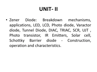
UNIT - II. PHYSICS OF SEMICONDUCTOR DEVICES. P- type semiconductors. Electron (minority carriers). Hole (majority carriers). -. -. -. -. -. -. -. -. Hole (mobile charge). Acceptor ions (immobile charge). -. (p ≈ N A ). -. ≈. N- type semiconductors.

UNIT - II
E N D
Presentation Transcript
UNIT - II PHYSICS OF SEMICONDUCTOR DEVICES
P- type semiconductors Electron (minority carriers) Hole (majority carriers)
- - - - - - - - Hole (mobile charge) Acceptor ions (immobile charge) - (p ≈ NA) - ≈
N- type semiconductors Electron (majority carriers) Hole (minority carriers)
+ + + + + + + + + Donor ion(immobile charge) Electron (mobile charge) (n ≈ ND ) + ≈
Formation of a PN-junction Ionized acceptors Ionized donors Junction P N + + + + + + + + Space charge region - - - - - - - - (OR) Depletion region Potential barrier height(V0) Potential barrier width (W)
Depletion region • The diffusing majority carriers from the • two regions recombine near the junction • and disappear. • The uncompensated acceptor and donor • ions set up an electric field which halts • the further recombination.
Space charge region • The two kinds of majority carriers diffusing across • the junction meet each other near the junction and • undergo recombination, leaving negative ions on • the p-side and positive ions on the n-side of the • junction. • This distribution of charges is called space charge • region.
_ + Diode symbol P N Cathode Anode
Energy diagram of a PN-junction (open circuit) Evp
From figure the following points to be noted: • Consider that a PN- junction has P-type & • N- type materials in close physical contact • with each other at the junction. • From figure, the Fermi level EF is closer to the conduction band edge Ecn in the N-type while it is closer to the valence band • edge Evp in the P-type.
The conduction band edge Ecp in the P-type • material is higher than the conduction band • edge Ecn in the N-type material. • Similarly, the valence band edge Evp in the • P-type material is higher than the valence • band edge Evn in the N-type material. • E1 & E2 indicate the shifts in the Fermi level from the intrinsic conditions in the P & N materials respectively.
Therefore, the total shift in the energy level • E0 is given by E0 = E1 + E2 = Ecp – Ecn = Evp - Evn • The energy E0(in eV) is the potential • energy of the electrons at the PN-junction, • which is equal to qV0. Where, V0= contact potential (OR) barrier potential ( exists across an open circuited PN- junction)
The diode can be operated in two different ways, as • Forward bias • Reverse bias
Forward bias When positive terminal of the battery is connected to the P-type & negative terminal is to the N-type of the PN-junction diode, known the diode is kept in forward bias.
Open circuit PN -junction P N Space charge region P N + + + + + + + + + + + + - - - - - - - - - - - - Forward bias VF
When the diode is in forward bias the following points are noted. • The applied +ve & -ve potential repels the • holes & electrons in P-type & N-type materials. • Hence, they can move towards the junction. • When the applied potential is more than the • internal barrier potential the depletion region • & internal potential barrier disappear. • Hence, high current flows through the junction. • In forward bias the current is due to majority • charge carriers (mA).
Reverse bias When negative terminal of the battery is connected to the P-type & positive terminal is to the N-type of the PN-junction diode, known the diode is kept in reverse bias.
Open circuit PN -junction P N Space charge region P N + + + + + + + + + + + + + + + + + + + + - - - - - - - - - - - - - - - - - - - - Reverse bias VR
When the diode is in reverse bias the following points are noted. • The holes move towards the –ve terminal of the battery & the electrons towards +ve terminal of the battery. • Hence, the potential barrier & width is increased • which prevents the flow of charges. • Therefore, no current flow across the junction. • But in practice a very small current flows in order • of microamperes, due to minority carriers.
Volt–Ampere characteristics (V-I curves) The graph is plotting in between the voltage is taking on X-axis & current is on Y-axis, is known as V-I characteristics of a PN- junction. Note: These curves are drawn on the basis of diode is connected in forward & reverse bias.
Forward bias I (i = mA) Knee voltage V 0
Reverse bias -V Breakdown voltage (i = μA) -I
I Forward bias i = mA Knee voltage V -V Breakdown voltage i = μA Reverse bias -I
From the graph the following points are noted. • The region between knee voltage & breakdown • voltage is known as non-ohmic region. • Above the knee & breakdown voltage the current • increases. • Breakdown voltage is due to thermally broken • covalent bonds. • Diode is conducting in forward bias & • non-conducting in reverse bias.
Applications of a diode • It works as an electronic switch. • It works as a rectifier. • It works as a demodulator(detector). • It works as a d.c. restorer in TV receiver • and voltage multipliers……
Diode as a rectifier: A rectifier is an electronic circuit which converts alternating current to direct current (OR) unidirectional current. Rectifiers are mainly three types 1.Half wave rectifiers 2.Full wave rectifiers 3.Bridge rectifiers
1.Half-wave rectifier: An electronic circuit which converts alternating voltage (OR) current for half the period of input cycle hence it is named as half-wave rectifier.
During the +ve half cycle of input,end A • becomes +ve w.r.t. B. Hence,the diode is • in forward biased.Therefore it offers • verysmall resistance conducts the current. • During the -ve half cycle of input, end A • becomes -ve w.r.t. B. Hence, the diode is • in reverse biased. Therefore it offers very • high resistance does not conducts the • current.
Rectifier efficiency(η) The ratio of D.C power output to applied A.C power input is known as rectifier efficiency. D.C. power output η = A.C. power input
D.C. power output = ( Im /π ) 2 x RL & A.C. power input = (Im /2 ) 2 x (rf + RL ) Therefore, ( Im /π ) 2 x RL (Im /2 ) 2 x (rf + RL ) η =
4 /π2 x RL = = Conclusion: 0.406 x 100% 40.6% rf + RL since, rf « RL η = The maximum efficiency of a half-wave rectifier is 40.6% of A.C power is converted into D.C power.
2.Full-wave rectifier: An electronic circuit which converts alternating voltage (OR) current into pulsating voltage (OR) current during both half cycle of input is known as full-wave rectifier.
During the +ve half cycle of input,end A • becomes +ve & B becomes negative. This • makes the diode D1 in forward biased & • D2 in reverse biased.Therefore, D1 • conducts while D2 does not conduct. • During the -ve half cycle of input,end A • becomes -ve & B becomes positive. This • makes the diode D2 in forward biased & • D1 in reverse biased.Therefore, D2 • conducts while D1 does not conduct.
Rectifier efficiency(η) The ratio of D.C power output to applied A.C power input is known as rectifier efficiency. D.C. power output η = A.C. power input
& D.C. power output = ( 2Im /π ) 2 x RL A.C. power input = (Im / √2 ) 2 x (rf + RL ) Therefore, (2 Im /π ) 2 x RL (Im / √2 ) 2 x (rf + RL ) η =
0.812 x RL = = Conclusion: 0.812 x 100% 81.2% rf + RL But, rf « RL The maximum efficiency of a full-wave rectifier is 81.2% of A.C power is converted into D.C power. Therefore, the full-wave rectifier efficiency is twice of a half-wave rectifier. η =
Diode equation 3/2 3/2 ( ) ( ) (EF – EC ) / KBT (EF – EC ) / KBT n = nc = Nc 2πme*KBT 2πme*KBT e e 2 2 (Diode current equation) h2 h2 The concentration of electrons in the conduction band of a semiconductor is given by (OR) ---- (1) Where, = Nc
3/2 ( ) (EV – EF ) / KBT nv = Nv 2πmh*KBT e 2 Similarly the concentration of holes in the valence band of a semiconductor is given by h2 ---- (2) Where, Eq(1) & (2) are applicable for intrinsic semiconductors . = Nv
For N-type semiconductor electron density is given by (EFn – Ecn ) / KBT (EFp – Ecp ) / KBT nn = Nc np = Nc e e Where, Where, In eq(1), nc = nn , EF = EFn , Ec = Ecn In eq(1), nc = np , EF = EFp , Ec = Ecp Similarly, for P-type semiconductor electron density is given by ---- (3) ---- (4)
For N-type semiconductor hole density is given by (Evn – EFn ) / KBT (Evp – EFp ) / KBT pn = Nv pp = Nv e e Where, Where, In eq(2), nv = pn , EF = EFn , Ev = Evn In eq(2), nv = pp , EF = EFp , Ev = Evp Similarly, for P-type semiconductor hole density is given by ---- (5) ---- (6)
Dividing the eq(3) with (4), we get, (EFn – Ecn ) (EFp – Ecp ) / KBT e e (Ecp – Ecn ) / KBT e nn nn = = np np Since the Fermi levels are equal , hence EFn = EFp Therefore, the above equation becomes as ---- (7)
As, Ecp – Ecn = eVB eVB / KBT - eVB / KBT Where, e e nn VB = the barrier potential = = np nn np Therefore, the eq(7) becomes as (OR) ---- (8)
Similarly, dividing the eq(5) with (6) & simplifying, we get, - eVB / KBT - eVB / KBT e e pn = = pn pp pp (OR) When the junction is in forward biased with voltage V, then the electron density in the P-region becomes as - e(VB -V) / KBT ---- (9) np + ∆np = nn e
eV / KBT eV / KBT e np + ∆np = np e - eVB / KBT e = np nn Since, Therefore, increase in electron density in the p-region is given by eV / KBT e ∆np = np - 1 ---- (10) - eVB / KBT (From eq(8) np + ∆np = nn e
When the diode is in forward bias more electrons are move from N-region to P-region hence, increase the Electron density in P-region by ∆np. Therefore, diffusion current of electrons is given by Where, C = constant (depends on the semiconductor) eV / KBT e ie= C1 ∆np = C1 np - 1 ---- (11) Similarly diffusion current of holes is given by
Therefore, total current is given by I = ie + ih eV / KBT eV / KBT e e ih = C2 ∆pn = C2 pn I = ie + ih = (C1 np+C2 pn) - 1 - 1 When the junction is in reverse bias V = - V , then the reverse current is given by ---- (12) -- (13)
At room temperature (T) - eV / KBT e « 1 Therefore, I = -(C1 np+ C2 pn) = I0--- (14) - eV / KBT e I = ie + ih = (C1 np+C2 pn) - 1 -- (13) since, I0 is the steady reverse current. Substituting eq(14) in eq(13), we get,