Download
1 / 49
510 likes | 529 Vues
Lateral Earth Pressure and Displacement of Geosynthetic Reinforced Soil (GRS) Walls Thang Pham, PhD Dept. of Civil Engineering UTRGV Nov. 16, 2017. Outline. Introduction of the GRS Application Literature Review of Design Methods for GRS Walls Behavior of GRS Composite

E N D
Lateral Earth Pressure and Displacement of Geosynthetic Reinforced Soil (GRS) Walls Thang Pham, PhD Dept. of Civil Engineering UTRGV Nov. 16, 2017
Outline • Introduction of the GRS Application • Literature Review of Design Methods for GRS Walls • Behavior of GRS Composite • Model for Lateral Stress and Displacement of a GRS Wall • Finite Element Analysis • Conclusions
GRS wall: GRS mass facing element GRS mass: compacted soil geosynthetic reinforcement Facing element: many types modular block facing is the most common Introduction a GRS wall with modular block facing
GRS wall: GRS mass facing element Introduction a GRS wall with reinforced concrete facing
Current Design Methods for GRS Walls • Prevailing design methods for GRS walls: • AASHTO method (2002) • NCMA method (Collin, 2002) • NHI method (Elias, et al., 2001) • based on design of “conventional” retaining walls with the addition of reinforcement acting as “tiebacks”
“Tieback” design concept: From Experiments Sv plays a much greater role than Tf.
Full-scale experiments (Adams, 1997; Adams, et al., 2007 ) Sv plays a much greater role than Tf.
Behavior of a GRS mass (continued) Unconfined Compression Test on “Mini Pier” (Adams, 1997 )
Behavior of a GRS mass (continued) Unconfined Compression Test (Elton and Patawaran, 2005 )
Full-scale experiments (Pham, 2009) Finishing Preparation of Specimen
Reinforcing Mechanisms • Concept of enhanced apparent cohesion(Scholosser and Long, 1972; Ingold, 1982) • Concept of increase of apparent confining pressure (Yang and Singh, 1974; Hausmann, 1976; Ingold, 1982, Athanasopoulos, 1994,) • Concept of reduced angle of dilation (Pham, 2009)
Reinforcing Mechanisms Concept of Apparent Cohesion Concept of Apparent Confining Pressure
The Model is developed Based on: • Schlosser and Long (1972): Concept of Apparent Cohesion • Ketchart and Wu (2001): Concept of Average Stress Analytical Model Strength Properties of a GRS Composite
Schlosser and Long (1972) Analytical Model Strength Properties of a GRS Composite Concept of Apparent Confining Pressure and Apparent Cohesion
FHWA-HRT-10-077 Proposed Model for Strength Properties of a GRS Composite GRS Integrated Bridge System Interim Implementation Guide (FHWA-HRT-11-206).
Model for Lateral Earth Stress and Lateral Displacement of a GRS Wall
Lateral Earth Stress of a GRS Wall • Due to the constraints to lateral deformation of a reinforced soil mass (resulting from frictional resistance at the soil-reinforcement interface), the lateral earth pressure against the wall face has been found much smaller than the lateral stress within a reinforced soil mass. • Field measured data have indicated that the lateral earth pressure varies little with depth in closely spaced reinforced soil walls; and that the AASHTO’s active earth pressure equation Eqn. (1) hardly applies.
Lateral Earth Stress of a GRS Wall • The lateral stress in the soil elements situated against the facing of a GRS wall, as obtained from FE analysis, is not equal to the lateral earth pressure. • The lateral earth pressure can however be deduced by distributing the load in the reinforcement layer adjacent to the facing over the tributary area of the facing based on equilibrium of forces.
Exiting Methods for Estimating Lateral Movement • FHWA Method (Christopher, et al., 1989) • Geoservices Method (Giroud, 1989) • CTI Method (Wu, 1994) • Jewell-Milligan Method (1989) (All ignored facing Stiffness)
h of the wall face at depth zi : Lateral Movement of GRS Walls (Cont.) (equation a) Prm = Reinforcement force at zone 1
Lateral Stress, Displacement and Connection Forces for GRS walls with Modular Block Facing • Assumptions: • The wall face is vertical or near vertical. • A uniform vertical surcharge is applied over the entire horizontal crest of the wall. • Each facing block is a rigid body: movement is allowed, but no deformation of the blocks.
Connection Forces of GRS Walls (cont.) A typical GRS wall with a modular block facing
Connection Forces of GRS Walls (cont.) (equation b)
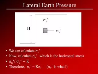
Lateral Earth Pressure of a GRS Wall with modular block facing
Lateral Erath Pressure of a GRS Wall with modular block facing
Estimating Lateral Movement of GRS Walls with Modular Block Facing • Movement of a GRS wall with modular block facing at depth zi can be determined as (substituting equ. (b) into (a)): • If the friction between the back of the wall face and the soil is ignored, the wall movement at depth zi can be determined as:
Lateral displacements of Jewell-Milligan method and the proposed method (with b = 0 kN/m3) Comparisons with Jewell-Milligan Method (1989)
Lateral displacements of Jewell-Milligan method and the proposed method (with b = 20 kN/m3) Comparisons with Jewell-Milligan Method (1989)(cont.)
Configuration of the Wall (Hatami and Bathurst 2005, 2006)
Compare the Analytical Modelwith Full-Scale Test Results by Hatami and Bathurst (2005 & 2006) (cont.)
Concluding Remarks • The lateral earth pressure against the wall face has been found much smaller than the lateral stress within a reinforced soil mass. • The analytical Model is capable of determining wall deflection as affected by the rigidity of wall facing, and overcomes a major shortcoming of the current method. • The Model can also be used to determine the connection forces at the wall face.