Download
1 / 29
290 likes | 571 Vues
Optical Network Resilience Ethernet Resilience and Resilient Network Time Domain Analysis. Luca Valcarenghi, Scuola Superiore Sant’Anna, Pisa, Italy, valcarenghi@sssup.it Filippo Cugini, Scuola Superiore Sant’Anna, Pisa, Italy, filippo.cugini@cnit.it

E N D
Optical Network ResilienceEthernet Resilience and Resilient Network Time Domain Analysis Luca Valcarenghi, Scuola Superiore Sant’Anna, Pisa, Italy, valcarenghi@sssup.it Filippo Cugini, Scuola Superiore Sant’Anna, Pisa, Italy, filippo.cugini@cnit.it Ricardo Romeral Ortega, UC3M, Spain, rromeral@it.uc3m.es David Larrabeiti, UC3M, Spain, dlarra@it.uc3m.es David Garcia Roger, UC3M, Spain, dgroger@it.uc3m.es
Outline Experimental Demonstration of Low-Cost 1:1 Optical Span Protection • Ethernet evolution • Survivability issues in Optical Ethernet networks • Proposed low-cost Optical Ethernet span protection system • Experimental demonstration
Ethernet Original Ethernet Frame: Preamble Destination Address Source Address Type Data FCS 8 6 6 2 46 – 1500 4 • Defines low-level (OSI Layer 1 and 2) data transmission protocol • Developed in mid-1970 and first published as IEEE 802.3 in 1985 • 10 Mbps over shared coax cable • Bus topology • Maximum distance 2.5Km (500m x 5 segments separated by repeaters) • Scope: LAN • Half duplex mechanism CSMA/CD (Carrier Sense, Multiple Access with Collision Detection)
Ethernet - First Evolution Repeater Bridge • Early 90s: 10BaseT From Coax cable to Unshielded Twisted Pair (UTP) cable • From Repeater/Hub (Layer 1) to Bridge/Switch (Layer 2) • From Bus topology to Star point-to-point topology • New MAC: Full Duplex Transmission without sharing the media No need of CSMA/CD
Fast Ethernet • 1995: IEEE 802.3u Fast Ethernet • 100 Mbps • 4B/5B Data Encoding (physical rate 125 Mbps, overhead 20%) • LAN scope • To maintain backward compatibility: • Same frame format and size • Maximum distance reduced to 100m (100BaseT) • Structured Cabling Standards • First*fiber utilization: • 100BaseFX with MultiMode fiber optic (maximum distance 2000m)
Gigabit Ethernet • 1998: IEEE 802.3z Gigabit Ethernet over fiber • 1000BaseSX, LX, CX • 1999: IEEE 802.3ab Gigabit Ethernet over copper • 1000BaseT • 1000 Mbps,8B/10B Data Encoding (overhead 20%) • To maintain backward compatibility: • Same frame format and size • Beyond LAN scope! • Today 1000BaseZX with SingleMode DS fiber (maximum distance 100 Km)
10 Gigabit Ethernet • 2002: IEEE 802.3ae 10 Gigabit Ethernet • Two families of Physical Layer (PHY) • LAN PHY (data rate 10Gbps) • WAN PHY (data rate compatible with SONET OC-192c) • Low overhead, 64B/66B code, scrambler based • Same frame format and size of previous Ethernet versions • Support for at least: • 300m over MM fiber • 10 km over SM fiber (1310nm) • 40 km over SM fiber (1550nm) • First 10GE implementations are using existing SONET/SDH infrastructures to transport Ethernet frames (WAN PHY)
Ethernet advanced features During Ethernet evolution some advanced features were introduced: • Automatic learning of MAC address • to allow plug and play • 802.1d Spanning Tree (ST) • To avoid loops and provide a slow fault tolerance • 802.1q Virtual LAN (VLAN) • To separate one physical network in many logical networks • 802.1s Multiple Spanning Tree (MST) • To allow separate spanning tree for each VLAN • 802.1p Priority Tagged Frame • To provide CoS features • 802.3ad Link aggregation • To increase bandwidth (multiple physical links joined into one logical link)
Optical Ethernet network scenario WAN MAN Mesh MAN Ring OAN Ring OAN Star Costumer premises Costumer premises • 1GE and 10GE over fiber optic media (Optical Ethernet, OE) allow connections between 10/100/1000 Ethernet LAN to OAN, MAN and WAN, combining lowest cost of equipments, simplicity and scalability with high and flexible bandwidth capability and large distances. • Ethernet goal: to be used as the unique end-to-end Layer 2 transport of IP packets in every region of the network, thus replacingSONET/SDH equipments (more expensive and less efficient for data transport)
Trends and opportunities WAN Legacy infrastructures (SONET ATM) MAN OAN Ethernet infrastructures Bottleneck in OAN-MAN LAN Current Bandwidth Availability 2000 2003-4 2010 • Driving factors: • Lowest cost and other Ethernet advantages • Need for eliminating the bandwidth bottleneck in OAN networks • Before completely replacing legacy infrastructures in every region of the network (first of all in Access), Ethernet has to rapidly solve some still existing issues
Ethernet challenges • The objective is to obtain the 50 msec restoration time that characterized SONET/SDH infrastructures. • Several resilient schemes acting both at layer 2 or 3 are proposed: • Rapid Spanning Tree Protocol (RSTP) • Resilient Packet Ring (RPR) • MPLS Fast Reroute • Limiting factors for the full deployment of Ethernet are: • Interoperability, scalability and standardization of Ethernet Services (VPN) • Management (centralized provisioning and monitoring) • Interworking with Legacy equipments • Reliability
Rapid Spanning Tree Protocol (802.1w RSTP) • 802.1d Spanning Tree acts at layer 2, taking about 50 sec to re-converge • 802.1w Rapid STP maintains backward compatibility. • RSTP allows pre-computed backup ports on Bridges: when a failure occurs, if the backup port is in Forwarding State, the physical connectivity can be restored in 10msec (best case) • However if Bridge (Switch) has no pre-computed port it is necessary to wait the exchange of BPDU on one of the remaining active ports (handshake) • This could take more than hundred of msec • higher than SONET 50 msec • Combining RSTP with Link Aggregation and Multiple ST the efficient utilization of resources and the recovery time performance increase, however these solutions are not sufficient to always guarantee the SONET restoration time
Resilient Packet Ring (RPR) • New MAC protocol (Layer 2 technology) • Requires 2 counter-rotating fiber ringlets • Increases Bandwidth efficiency using Spatial Reuse • QoS (High,Medium and Low service classes) • Restoration within 50 msec • Steering(all stations are notified of the entire topology and of the failure location: the transmitting stations choose the ringlet that does not contain the failure) • Wrapping (station adjacent the failure wraps traffic to other ringlet) • Protection hierarchy (for simultaneous failures) Customer Premises • New MAC not supported by most of equipments • Requires specific network topology (ring) • Current RPR interfaces are generally included into more expensive layer 3 equipments, where other efficient resilient solutions are possible without the topology constraint. CO
MPLS Fast Reroute LSR Source LSR Dest • MPLS label stacking capability to nest all the failed LSPs into one protection LSP (Label Switched Path). • Very fast and efficient for every topology • Covers link and path failure • Protection against node failure is achievable however the detection time based on hello packets takes seconds • Requires the availability of spare alternative paths and nodes • Every node must be an expensive Layer 3 IP/MPLS Router
OAN Star Protected Design Customer Premises CO • Typically implemented in Optical Access Networks (OANs) • Layer 2 switches at costumer premises and Layer 3 router at the Central Office (CO) • Every Optical Ethernet (OE) connection is protected with a dedicated point-to-point link • Besides the fiber availability it requires the presence of many OE interfaces. • The cost of Layer 2 equipments and ports is decreasing but, if the costumer (e.g. company) requires Layer 3 routers, the cost is a key issue
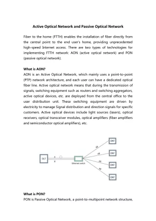
1:1 Optical Span Protection implementations Layer 3 IP Router Layer 3 IP Router Working GE GE Backup FE FE Linux Box Linux Box • Particularly suitable for point-to-point OAN connections based on Optical Ethernet between Layer 3 Routers (avoids the duplication of expensive data ports) • Three failure detection mechanisms are presented. • Solution based on four 2x1 optical switches and two Linux Box • Initially the primary fibers are used • If a failure occurs the backup fibers are used TTL TTL
Software detection mechanism based on SNMP SNMP DOWN Switch Command Layer 3 IP Router GE Linux Box FE • Linux Box and IP Router communicate through a UDP socket over Fast Ethernet local connection • When a failure occurs the Router sends a SNMP (Simple Network Management Protocol) message to the LB • After receiving the message the LB emits the switch command
HIGH HIGH Pin Vref LOW Control Circuit Switch Command Hardware detection mechanism based on Loss of Light (LoL) Layer 3 IP Router GE Linux Box TTL • The received optical signal is split in two fibers part of the signal enters in the control circuit. • When a failure occurs the output of the circuit becomes LOW the LB emits the switch command
Experimental demonstration • The proposed solutions have been extensively tested with commercial Routers and Opto-mechanical switches (~7ms of switching time) • Working fibers have been interrupted >100 times for each solution • The time required for the Linux Box to elaborate the fault reported by the detection mechanisms and to send the right command to the switches is negligible (only few microseconds). • The recovery schemes always succeeded. However, different recovery times have been experienced for the hardware and software solutions. Both software solutions (Polling and SNMP) achieve the same recovery time
Typical Outage Time Performance: software solutions (Polling and SNMP) A. Failure B. Router detects the failure and sends DOWN Message: connectivity is immediately re-established • The router verifies and updates, by default, the state of its interfaces once a second: a uniform distribution in the range 80-1080 ms has been observed for A B • From 1 to 2 seconds elapses before the interface is declared up again (B C)
Outage Time Performance: hardware solution • The speed of this solution is only limited by the switching time of the 2x1 switches, which is approximately 7 ms Constant outage time of 7 ms has been observed
Considerations and Comparison • Control LB (or equivalent device) is not strictly necessary. However it may allow: • explicit lightpath provisioning over the selected fibers • remote verification of the protection system integrity • signaling to a system manager of failure occurrence • Combination and coordination of the three solutions to achieve high reliability If the HW solution does not successfully operates, the slower SNMP solution can intervene. Polling solution can be used, if SNMP does not detect the failure, as well as to verify the system integrity. • Besides the large recovery time (higher than SONET 50msec), the software methods have a second drawback: loss of OSPF entries in the routing table After the physical connectivity has been recovered, it is necessary to wait until the OSPF routing entries are restored to resume full operation of the router ( >30 s )
Solutions suitable for OAN networks • The proposed solutions represent a viable proof of concept for the implementation of low-cost reliable OAN connections between Optical Ethernet interfaces of Layer 3 IP Routers: the solutions do not require port duplication. • Economical evaluation (provided fiber duplication is not an issue): • 1 Gigabit Ethernet interface of a commercial IP router vs. • Two 2x1 optical switches + Control Circuit + Embedded Linux Box GE costs about 10 times the proposed protection scheme (our experience) • The presented solutions does not detect signal degradation such as excessive Bit Error Rate (BER) due to physical transmission impairments (e.g. Polarization Mode Dispersion) However it does not represent an important limitation: in OANs fiber cut is the most important cause of failure.
Conclusions • Optical Ethernet represent one of the most interesting solution for eliminating the bandwidth bottleneck between high-speed LAN and optical MAN core. • The limiting factor for the full deployment of OE is represented by the lack of some OA&M features, such as reliability. • The experimental results of three failure detection techniques and fast protection activation for 1:1 Optical Ethernet link protection are presented. • The solutions differ in recovery speed, realization complexity, and separately or jointly are suitable to be integrated in the control plane of an automatic switched optical network. • Using these solution the overall cost of the protection system is greatly reduced.
GMPLS control plane • Allows full control of the elements of the network • Provides the following functionalities • Neighbor discovery • Dissemination of link status • Typology state management • Path management • Link management • Protection and recovery
LINK PROTECTION GMPLS
New object/TLV (1) • Optional, carries protection information • Link protection type of a requested LSP • Particular types like 1+1, or 1:N • Connection request processed only if the desired protection type can be guaranteed • GMPLS advertises the protection capabilities of a link in routing
New object/TLV (2) • Path computation algorithms • may take this information into account when computing paths for setting up LSPs • Additional use of Protection Information • Indicates if the LSP is a primary or secondary LSP • Secondary LSP is a backup to a primary LSP • Secondary LSP is not used until the primary LSP fails
Support of the LSP • Six types of individual link protection defined • Enhaced • It needs a protection more reliable than dedicated 1+1 • Dedicated 1+1 • Dedicated 1:1 • Shared • Needs shared protection (such as 1:N) • Unprotected • Extra Traffic • Use links that are protecting other (primary) traffic • But if primary traffic links fail, the LSP will be preempted • May be combined