Understanding the Role of Lenses and Optical Stops in Imaging Systems
This overview discusses the finite nature of lenses and optical stops, elaborating on key components such as Aperture Stop (A.S.), Field Stop (F.S.), Entrance Pupil, Exit Pupil, and Chief Ray. It explores how these elements impact the energy and information that optical systems capture and image. Additionally, the relationships between lens speed, f-number, and exposure times for cameras are detailed. Important concepts such as marginal rays, the behavior of plane mirrors, and characteristics of conic sections like parabolas and prisms in light behavior are also examined.

Understanding the Role of Lenses and Optical Stops in Imaging Systems
E N D
Presentation Transcript
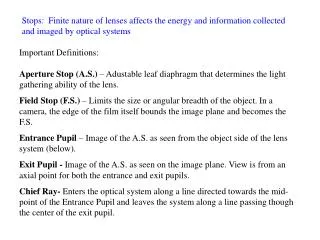
Stops: Finite nature of lenses affects the energy and information collected and imaged by optical systems Important Definitions: Aperture Stop (A.S.) – Adustable leaf diaphragm that determines the light gathering ability of the lens. Field Stop (F.S.) – Limits the size or angular breadth of the object. In a camera, the edge of the film itself bounds the image plane and becomes the F.S. Entrance Pupil – Image of the A.S. as seen from the object side of the lens system (below). Exit Pupil - Image of the A.S. as seen on the image plane.View is from an axial point for both the entrance and exit pupils. Chief Ray- Enters the optical system along a line directed towards the mid-point of the Entrance Pupil and leaves the system along a line passing though the center of the exit pupil.
Aperture Stop (A.S.) – Adustable leaf diaphragm that determines the light gathering ability of the lens. Field Stop (F.S.) – Limits the size or angular breadth of the object. In a camera, the edge of the film itself bounds the image plane and becomes the F.S. Entrance Pupil – Image of the A.S. as seen from the object side of the lens system (below). Exit Pupil - Image of the A.S. as seen on the image plane.View is from an axial point for both the entrance and exit pupils. Chief Ray- Enters the optical system along a line directed towards the mid-point of the Entrance Pupil and leaves the system along a line passing though the center of the exit pupil.
Another Example showing a more complex arrangement. Marginal Ray – Ray from the outermost object point on the axis that goes through the A.S.
Relative Aperture and f-number: f/# = f/D Let Io·Aobj represent the power radiated spherically by an object at the point 2f behind a lens. See next slide E.P. E.P. D 2f f f 2f Therefore, the time necessary for photographic exposure is proportional to (f/#)2 = speed of the lens. So, an f/1.4 lens is twice as fast as an f/2 lens since the time necessary for the same exposure (I·t) is ½. On cameras, e.g., f/# = 1.4, 2, 2.8, 4, 5.6, 8, 11, 16, and 22; so exposure times of 1, 2, 4, 8, 16 msec for each consecutive setting are necessary to obtain the same amount of energy absorbed in the photographic film. f/2 f/4 D D/2
Plane Mirrors i=r , So and Si < 0 when they lie to the right of V. The image is invariably virtual in which it is (1) erect and (2) inverted. Reflection from a single mirror causes a right-handed (r-h) object to appear as a left-handed (l-h) image. The transverse magnification is simply MT = -Si/So = +1 Systems with more than one mirror give rise to an odd or even number of reflections, resulting in r-h l-h or r-h r-h symmetry, respectively. ir SoSi
l-h r-h Inversion
Plane Mirrors l-h r-h Inversion
Multiple mirrors can be used to control the parity of the image by creating more than one symmetry inversion.
Aspherical Mirrors: The symmetry of incoming plane waves along the optical axis gives
Parabola Directrix 4py = x2 p = distance from vertex to focus (or directrix) Eccentricity (e) is defined as follows: e = FP/PQ = 1 for a Parabola Other conic sections: hyperbola or hyperboloid (e > 1) ellipse or ellipsoid (e < 1 )
There are many introductory web-sites that describe conic sections, e.g., http://math2.org/math/algebra/conics.htm, but be sure to refer to your math text books.
The type of section can be found from the sign of: B2 - 4AC The Conic Sections. For any of the below with a center (j, k) instead of (0, 0), replace each x term with (x-j) and each y term with (y-k). By changing the angle and location of intersection, we can produce a circle, ellipse, parabola or hyperbola; or in the special case when the plane touches the vertex: a point, line or 2 intersecting lines.
Using spherical sections to approximate parabolic reflection: Consider |y/R| << 1 and x < R, use a binomial expansion y Paraxial regiony << R Equation for a parabola
Paraxial Approx. f > 0 (concave mirror); f < 0 (convex mirror) Also, as before, Note: si on the left of V is now taken as positive; opposite to the lens system Similar behaviors and properties: concave mirror convex lens convex mirror concave lens
Fig. 5.55 The image-forming behavior of a concave spherical mirror.
Consider a dispersing prism which can be used to perform spectroscopy as shown on the left.
Dispersing Prism: The emerging ray will be deflected (refracted) by an angle from the original direction. Consider the basic geometry:
Using Snell’s law: • Thus, as n increases then also increases. • So n decreases as increases (see figure 3.40) • and n increases as decreases. • (Red) < (Blue) (can also be seen in the figure with colors). The smallest value of , the minimum deviation, m, is important.
The symmetry of these angles must therefore produce a ray parallel to its base for the minimum of (m). The symmetrical ray transfer (parallel to its base) gives the following: Therefore, we can experimentally determine n() by measuring the minimum angle of deviation m() for light rays having different .
nm First, we need to make a prism out of the transparent material having the cross-section of an isosceles triangle. m By finding m for each ray having a different , we can determine n().
r-h r-h Fig. 5.61 The right-angle prism Fig. 5.62 The Porro prism. The orientation is reversed but remains right-handed. Reflecting Prisms shown here are used to change orientation and handedness. Some of the surfaces are silvered if TIR conditions aren’t met, such as c = 42 for n = 1.5.
Notice that prisms can be constructed according to requirements of size, shape, angle, etc… Fig. 5.66 The penta prism and its mirror equivalent. Same orientation and remains r-h. r-h r-h
Fiber Optics: Rays reflected within a dielectric cylinder Snell’s Law: Path length traversed by the ray (l): Number of reflections (N) in the cylinder: t The sign indicates that N depends on where the ray strikes the face of the cylinder. D = q D sin x t t D x
For example, if nf= 1.6, i= 30, D = 50 m Then # reflections per length = N/L = 2000/feet = 6,600/meter To prevent cross-talk, must use a cladding. Typically the fiber core has nf = 1.6 and the cladding has nc = 1.5. Rays that are incident (picture on the right) with angles greater than max will strike the interior wall at angles less than c, and will leak out of the fiber. Therefore, max , which is the acceptance angle, defines the half-angle of the acceptance cone of the fiber. corecladding i = max
c - Critical angle at the core-cladding interface for TIR tc – Critical angle for the transmitted ray at the core-air interface )c + tc = 90) max- Maximum angle for the incident ray, beyond which there is no TIR at the core-cladding interface NA2 isa measure of the light-gathering power of the system and originates in microscopy where the equivalent expression describes the capability of the objective lens. The NA is related to the speed of the system by
Consider the acceptance cone for an optical fiber: L rmax max max x The collected intensity (irradiance) I rmax2 sin2max NA2 (f/#)-2
Consider attenuation in optical fibers Decibel (dB) is the customary unit for indicating ratio of two power levels: dB= - 10 log (Po/Pi(and e.g. 1/100 20 dB Attenuation () is in dB/km of fiber length L L = -10 log(Po/Pi( • Quality of Optical Glass • 1965 1000 dB/km () • 20 dB/km • 1982 0.16 dB/km Improvements in fabrication of fibers and removal of metallic impurities like Fe, Ni, Cu and removal of H20 and OH- have led to the dramatic reduction in fiber attenuation (). Today, reamplification after every ~80 km is needed after a ~50 dB drop in signal.
Intermodal Dispersion (IMD) The minimum and maximum transit times for a ray traversing a distance L in the fiber are The spreading out of signals due to this effect is known as IMD
Three basic types of Optical Fibers each with different IMDs Multi-mode Suffers greatly from IMD; core is 50-200 m and cladding is 20 m thick. Graded core diameter is about 20-90 m. Graded index cores can reduce IMD by factor of 100, due to the spiraling effect and index-dependent speed of the rays.IMD of 2 ns/km is typical here. Core diameter is less than ~10 m and typically from 2-9 m. Low attenuation of 0.2 dB/km; currently ideal choice for long-haul communication networks today. Single mode fibers are the best solution for IMD since only one horizontal mode with its ray traveling parallel to the axis can propagate.
Imaging “coherent” fiber bundle Collection of individual parallel fibers for image transfer applications Fig. 5.73 Intermodal dispersion in a stepped-index multimode fiber. Higher-angle rays travel longer paths. Fig. 5.75 The spreading of an input signal due to intermodal dispersion (IMD).