Download
1 / 28
340 likes | 1.06k Vues
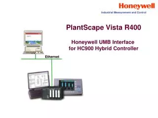
Industrial Measurement and Control. PlantScape Vista R400. Honeywell UMB Interface for HC900 Hybrid Controller. Ethernet. Interface to HC900. PlantScape Vista R400 Driver Requirement: Honeywell *UMB Interface (HC, UMC, UDC, DR, DPR, Trendview).

E N D
Industrial Measurement and Control PlantScape Vista R400 Honeywell UMB Interface for HC900 Hybrid Controller Ethernet
Interface to HC900 • PlantScape Vista R400 Driver Requirement: • Honeywell *UMB Interface (HC, UMC, UDC, DR, DPR, Trendview) *UMB =Universal Modbus, a Honeywell term. The driver uses the documented Modbus address map that applies to many Honeywell products in common. It means that the Modbus addresses for similar parameters in different products are the same, or “universal”.
Product Support PlantScape Vista R400 UMB Interface Supports: • UDC 2300, 3300, 5300 Controllers (serial) • DPR 180, 250 Recorders (serial) • DR 4300, 4500 Recorders (serial) • VPR100, VRX 100, 180 Recorders (serial) • UMC800 (serial) • HC900 (Ethernet) • TrendView Recorders (Ethernet)
Database Preparation Prior to QuickBuilder Database entry: • Print out the following HC Designer Reports for each HC900 • configuration: • Tag Information Report – lists all Signal Tags and Variables by • number with tag names and descriptors for association • Note: This report is called Tag Information>Signal Tags and Variables • in HC Designer 2.1 and later • Block Modbus Addresses – lists major (principal) blocks by • number such as loops, setpoint programmers, sequencers, etc. • Note: This report is called Modbus Register Map>Summary Function • Block Report in HC Designer 2.1 and later The numbers entered for HC900 control loops, signal tags, variables, etc. in QuickBuilder correspond to those listed in these reports.
QuickBuilder Database Generation • (The actions below assume the Honeywell UMB driver has been enabled • for a new project) • A. Add Channel, selecting Universal Modbus as Channel Type • B. Define Virtual Controller (s) for each HC900 • Controller 1 (Offset=0): Control loops 1-24, Variables, SP Programmers 1-4 • Controller 2 (Offset=2000): Signal Tags 1-1000, SP Scheduler 1 • Controller 3 (Offset=4000): Sequencer, Signal Tags 1001-2000 • Controller 4 (Offset=6000): Loops 25-32, Scheduler 2, • HOA, Device Control, Alternator, Stage, Ramp functions • (NOTE: Most applications will require 2 virtual controllers) • C. Define Points: • Uses acronyms (names) for HC900 point entry, e.g., LOOP 1 PV, • LOOP 2 GAIN1, TAG 34 (for Signal Tag 34), MATH_VAR 7 (for Variable 7), etc. • Analog Point Examples: Control loops (up to 8 parameters / loop, • composite point), Analog Signal Tags, Analog Variables, Analog Inputs, etc. • Digital Status Point Examples: Digital Signal Tags, Digital Variables, Digital I/O • Use Hex addressing for non-named parameters
QuickBuilder Channel Setup Channel Setup for HC900 Port Tab Select Ethernet port type via “LANVendor” selection and “Modbus” protocol for Port Name
QuickBuilder Controller Setup Controller Setup for an HC900 Enter Device Type (HC900) Assigned to Channel Name Enter Device Identifier (1), Direct E-Net to an HC900 Enter IP address of the controller Enter Offset (if needed). Needed for Signal Tags & higher Modbus addresses, see Slide 8)
Controller Offsets Multiple virtual Controllers, each supporting a 2000 Hex Address range, are needed to cover the range of Modbus Addresses for the HC900 driver Note: 4 “virtual” Controllers required for complete HC900 data access (2 is typical). Offset Entry = 0, 2000, 4000, or 6000 hex
QuickBuilder Point Setup Composite Point Setup (Analog) for a Control Loop (Controller Offset =0) SP,Output, Mode (A/M & R/L) Addresses Point Acronym, “LOOP 1 PV” PV Source Address Definition
QuickBuilder Point Setup (Cont.) Point Setup (Analog) for a Control loop - Detail of other Analog Point Entries “Control” Tab Entries Typical “Auxiliary” Tab Entries
QuickBuilder Point Setup (Cont.) Point Setup for Signal Tags and Variables (Controller Offset = 2000) Note: It is necessary to print out the Tag Information Report from the HC Designer configuration for the listing of Signal Tags and Variables configured. The TAG # entries in the QuickBuilder database correspond to the Tag or Variable number listed in this report.
QuickBuilder Point Setup (Cont.) Point Setup using Hexadecimal Modbus Addressing Note: For parameter addresses that are not within the named address space supported by the driver, hexadecimal Modbus addressing must be used. These are classified as “Non-named” addresses. It will be necessary to use the HC900 Communications User Manual as a reference, #51-52-25-111. Examples: Parameter Point Entry Data Format Controller Offset 6000 IEEEFP (assumed) 4:0x7840 Analog Point - LOOP 25 PV Floating Point Holding Register Hex Address Analog Point - Analog In, Rack 1, Slot 1, Channel 8 IEEEFP (assumed) 0 3:0xE Analog Point - Analog In, Rack 2, Slot 2, Channel 2 IEEEFP (assumed) 0 3:0x112 Hex Address Input Register 4000 Analog Point -Step Number of Sequencer 1 4:0x5AA9 UINT2 Unsigned Integer
Standard Station Group Displays Group Display for Control Loops using UMB Interface Analog Composite Points for control loops Mode Selections: AUTO-LSP AUTO-RSP MAN-LSP MAN-RSP
Station Display – Point Detail Point Detail for Analog Point (Control loop)
HC900 SP Programmer Interface • The SP Programmer / Recipe Interface is standard • (for HC900 and UMC800) • - Part of Honeywell UMB Interface • - Support for SP programmers 1 -4 • - SPP Interface Display selection is added into Station menus • - Only Requires 1 Database Point per Programmer • - Create SP Programs, Recipes, and “Combined Recipes” • SP Programs - Up to 1000 • Recipes (50 parameters) - Up to 1000 • Combined Recipes (1- 2 SPP’s + Recipe (50 parameters)) • - Uses a SP Programmer Tabular Segment Display for • Configuration and Operator display • - Has SP Profile pre-plot display with PV trend (Primary & Aux Out)
SP Programmer Point Setup Point Setup for HC900 and UMC800 (SP Programmers 1 to 4) Main Tab (Controller Offset = 0) Enter Point ID (need to reference this on SP Programmer summary display showing status of the 4 programmers) Enter PV for Primary trend Plot (primary loop PV) Enter PV Range
SP Programmer Point Setup (Cont.) Control Tab Enter SP Source Address Identify number of the SP Programmer (1,2, 3, or 4)
SP Programmer Point Setup (Cont.) Auxiliary Tab Enter PV of Aux SP (if Used) for Aux SP Trend Enter as Shown for Progrmr #
SP Programmer Point Setup (Cont.) Using Alarms tab, enter limits for Primary And Auxiliary (if used) SP Programmer Output Range of Primary SP Output for trend plot Range of Auxiliary SP Output for trend plot Select Alarm Types, PVHigh and PVLow for Primary and Auxiliary SP Ranges Enter Disable Alarming selection Enter History selections as shown below
PlantScape Menu Selections for HC900 (Menu additions are part of UMB Interface) Selections from Configure Menu Configure SP Profiles SPProgrammers Access Configure: Recipes (Variables) or,Combined Recipes(Up to 2 SP Programmers plus 50 Recipe Variables)
SP Programmer/Recipe Displays SP Programmer Summary Display (Access to “Programmers”) Must enter Point ID for the Analog Point configured for the SP Programmer, in this case SPPPRGMR_1
SP Programmer Tabular Display For On-line Operation One of first 4 Programmers/Controller (SPP1, SPP2, SPP3, or SPP4) Access SPP Trend Page Controller Selection Status Programmer Selection Primary & Aux Status Present Segment Up to 50 Segments, 10 segments shown) Start, Hold, Adv, Reset Allows upload from controller in SPP Ready Mode Download in SPP Ready Mode
SP Programmer Trend Display SP Profile Pre-plot and PV Trend Selection of Primary or Auxiliary Out Plots Go to SPP Program Page SP Program Pre-Plotted (Yellow) Total Program Span in Hrs or Min SP Program PV (Cyan, blue) Profile Name Start, Hold, Adv, Reset Program Status
SP Profile Setup • Configuring SP Profiles in PlantScape Vista • Up to 50 segments each • Up to 1000 stored Named Profiles Configured and Selection
HC900 Setpoint Profile Setup Configuring SP Profiles Name the profile Enter Ramp Type, Ramp or Time based Extensions for cycles Select Ramp or Soak, Segment Values, Events Copy a profile for easy edit
Recipe Support Part of Universal Modbus Driver for HC900 / UMC800 • Recipes (Variables Only) • Configurable for up to 50 Variables • Variables are selected by uploaded Tag Names • Downloads to Variables assigned to recipe • Store up to 1000 recipes in PlantScape • Combined Recipes • Combines Up to 2 Set Point Profiles and a • Recipe (Variable) list for download • Variables are selected by uploaded Tag Names • Store up to 1000 Combined Recipes in PlantScape
Combined Recipe Setup Combined Recipes are 1 or 2 SP Programmers + a 50 Variable Recipe, stored / downloaded in combination to compatible controllers and SP programmers Name the Combined Recipe Select 1 or 2 SP programs Select Recipe with Variables Assign to Compatible Controller and SP Programmer Numbers
Recipe Setup (Variables) Up to 1000 Recipes (containing HC900 Variables only) can be stored in PlantScape Vista • Recipes can have up to 50 Variables from HC900 configuration • Recipes can include SP profile numbers (if profiles are stored in controller ) • Recipes can be “combined” with SP profiles (see Combined Recipe Setup slide), • assumes SP profiles and Recipes are stored in PC HC900 Variables selected by tag names uploaded from controller Values entered For recipe