Download
1 / 10
100 likes | 111 Vues
This presentation reviews the fast and slow data logger configurations of the HL-LHC Vertical Magnet Test Stand at Brookhaven National Laboratory. It covers the capabilities of the data loggers, the signals captured and monitored, the isolation of voltage tap signals, the monitoring of IGBT switches and strain gages, and the computer interfaces for controlling the loggers and power supplies.

E N D
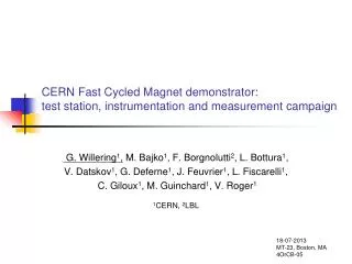
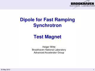
Hi Lumi Magnet Test StandFast and Slow Data Logger Piyush N Joshi Superconducting Magnet Division Brookhaven National Laboratory Upton NY 11973 USA Review for HL-LHC AUP Vertical Magnet Test Stand at BNL-August 1-2, 2018
Outline Slides in this presentation addresses charges 3c and 3e Adequate systems for QPS, interlock and monitoring Fast logger configuration Slow logger configuration Voltage tap signal isolation IGBT fast and slow logger Strain gage scanner Computer interface (HMI) Review for HL-LHC AUP Vertical Magnet Test Stand at BNL-August 1-2, 2018
Fast logger is used to capture transient voltages of the magnet during quench. The trigger for capture is generated by quench detector • 200 channels sampled simultaneously at 10KHz with 10,000 pre triggered samples and 40,000 post triggered samples giving transient capture window of 5seconds. • Signals captured are: voltage taps on the coil; Magnet current, power supply voltage; quarter, half and full coil voltages; splice joint signals; quench heaters’ currents and voltages; ground current; quench antenna signals; test dewar pressure, temperature and few other signals of interest • Two National Instrument PXIe-1075, 18 slot chassis with real time controller • 25 DAQ modules each with 8 differential input, 16bit, simultaneous sampling. Max sampling rate of 250KHz Fast logger Review for HL-LHC AUP Vertical Magnet Test Stand at BNL-August 1-2, 2018
Slow logger is used to log and monitor various test parameter during test. • 56 channels sampled at 1KHz. Each signal processes through 3 power line cycle averaging filter. • Signals monitored while ramping the magnet are: Magnet current, power supply voltage; quarter, half and full coil voltages; splice joint signals; ground current; test dewar pressure, temperature, liquid helium level, voltage drop across high current bus work and few other signals of interest • One National Instrument PXI-1050, 8 slot chassis with real time controller • DAQ modules are differential input, 16bit, multiplexed sampling. • Many similar slow logger and monitors are installed in cryogenic plant. Slow logger Review for HL-LHC AUP Vertical Magnet Test Stand at BNL-August 1-2, 2018
All magnet voltage tap signals are isolated before connection to DAQ modules • Isolation is provided by ‘off the self’ modules made by Verivolt model IsoBlock Q. Each module has 4 channels • Galvanic isolation between Input to output=2500V • Common mode and differential mode surge voltage withstand=1500V • Jumper selectable Input range available from 200mV to 1000V. Output =+/-10V • Total of 160 Isolated channels Available for connection to data loggers. Isolation IsoBlock-Q Review for HL-LHC AUP Vertical Magnet Test Stand at BNL-August 1-2, 2018
Each 12KA solid state switch used in energy extraction comprise of six high current IGBTs in parallel. It is an complex assembly consisting of snubbers, drivers, transient suppressors, current and voltage monitors. • We have two such switches so basically we have 12 IGBTs in parallel. • It is extremely important that each IGBT share equal current (sharing should be with in 10%) during turn off. • Each IGBT is monitored for the current sharing, temperature and voltage across them (Vce) during steady state or ramping operation. Each switch has 32 channel slow logger • Long term trend of Vce provides good indication of the health of the IGBT • Each switch also has its own 12 channel transient data recorder operating at 50KHz to capture high voltage Vce of each IGBT during shutoff IGBT switch datalogger Review for HL-LHC AUP Vertical Magnet Test Stand at BNL-August 1-2, 2018
Two systems for two type of strain gages • 40 Channel simultaneous sampling HBM make strain gage read out system for “CERN” type gages • 60 Channel multiplexed readout system based on Agilent model 34970A. This system is used for “LARP” type gages. Programed in LabView • GPIB interface with magnet test control room • Agilent system has accuracy of 45uV over 1V range. • LARP type strain gages are configured with six independent excitation current circuits Strain Gage Scanner HBM Scanner Agilent Scanner Review for HL-LHC AUP Vertical Magnet Test Stand at BNL-August 1-2, 2018
All core software for fast and slow loggers is written in LabView Real Time • Windows PC in main control room interfaces with real time systems on a private network for operator interface. Computer interface for loggers Slow logger and PS Control Review for HL-LHC AUP Vertical Magnet Test Stand at BNL-August 1-2, 2018
Computer interface for loggers Quench Heater Power Supply Control Interface Review for HL-LHC AUP Vertical Magnet Test Stand at BNL-August 1-2, 2018
Questions ? Review for HL-LHC AUP Vertical Magnet Test Stand at BNL-August 1-2, 2018