Application example
Application example. Power Plants SCR S elective C atalytic R eduction Ammonia – Ammonia/Water (NH 3 – NH 3 /H 2 O)

Application example
E N D
Presentation Transcript
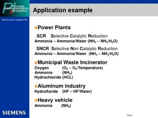
Application example • Power Plants • SCR Selective Catalytic ReductionAmmonia – Ammonia/Water (NH3 – NH3/H2O) • SNCR Selective Non Catalytic Reduction Ammonia – Ammonia/Water (NH3 – NH3/H2O) • Municipal Waste Incinerator Oxygen (O2 – O2/Temperature) Ammonia (NH3) Hydrochloride (HCL) • Aluminum industry Hydrofloride (HF – HF/Water) • Heavy vehicle Ammonia (NH3)
Application example SCR on Coal Power Plant Inject NH3 in the raw gas Minimize slip to the air pre heater Monitor NH3 in situ Optimizing cleaning cycles NH3 + NOx N2 + H2O
Application examplePerformance demand NH3 slip at SCR • Environment after SCR for NH3-slip • Range: 0 – 10 ppm • Resolution: ± 0,3 ppm • Response time: approx. 1 – 30 seconds • Path length: 3 – 10 m. • Dust load: < 15 g/Nm3 • Temperature: < 650 °C • Flange: DN65/PN6 alt. 4 “ ANSI / 150 lbs • Purge media: Air blower or instrument air • The demand • To measure below 2 ppm of ammonia in high dust load.
Application exampleMunicipal Waste Incinerator NH3-sensor O2/temp-sensor HCl-sensors H2O-sensors
Application exampleMetallurgy Electro oven Converter Heating oven
CD 3002 Installation Examples • Good and bad set-up • Ammonia application • Oxygen application (Combustion control) • Heavy vehicle application • Miscellaneous • Placement of sensors • Wedge-modules • Purging tubes
CD 3002 Installation exampleAmmonia application – Good setup
CD 3002 Installation example Oxygen application – Good setup
CD 3002 Installation example Heavy Vehicle application – Good setup
CD 3002 Installation example Heavy Vehicle application – Bad setup
Pre-Installation Checkpoints LDS 6 Customer flange installed and aligned Purging media prepared at Customer flange Cabling (Hybrid and Loop) prepared Location of Central Unit prepared Modem (optional)
Installation Checkpoints LDS 6CD6 Sensors Verify the customer flange, using the Flange alignment kit (optional) Install the sensors and connect the purging media Connect the fiber optics Align the sensors
Installation Checkpoints LDS 6Central Unit • Install the Central Unit in it´s cabinet / rack • Connect the fiber optic(s) • Power-up the analyzer • Make sure that all parameters are correctfor the channel(s) • Path length • Cable length (Hybrid cable) • Process temperature, Manual or External input (for external, see next page) • Process pressure, Manual or External input (for external, see next page) • Response time (Primary gas) • Measured Unit (Primary gas) • Range measured, corresponds to the 4-20mA output (Primary gas) • Response time (Secondary gas) • Measured Unit (Secondary gas) • Range measures, corresponds to the 4-20mA output (Secondary gas) • Transmission Alarm (factory set on 15%)
Installation Checkpoints LDS 6Central Unit • Set the transmission RMS ( do not exceed 300 ) • If the customer has external temperature / pressure input the range for the 4-20mA input signal have to be verified. Temperature: • In T Min (4mA) • In T Max (20mA)Pressure: • In prs Min (4mA) • In prs Max (20mA)
Trouble shooting CD6-Sensors • Most faults are caused by miss-alignment of the sensors, dirty lenses or the light-path being blocked by dust • Fault: Transmission RMS drops slowly • Cause 1: The lenses are getting dirty Action: Clean the optics and verify that the purging is working • Cause 2: Build-up of dust in or in front of the purging tube Action: Remove the dust-pile. Try to improve the purging • Cause 3: The sensors have moved due to a temperature change Action: Re-align the sensors • Fault: The transmission RMS drops suddenly • Cause 1:There is no 24 VDC to the detector card Action: Check cables for damages. Check if there is 24 VDC from the LDS6 all the way out to the detector card in the Receiver sensor box. • Cause 2: The detector card is broken Action: Replace the detector card.