Download

1 / 31
310 likes | 429 Vues
Technical Details of the T2K Horns. L. Bartoszek BARTOSZEK ENGINEERING NBI2006. My part in T2K. I have been working with Ichikawa-san and the KEK group on horns 1 and 3 I model the design in 3D (with much iteration with KEK group,) and Toshiba builds it

E N D
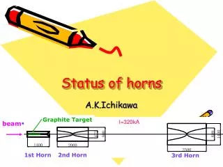
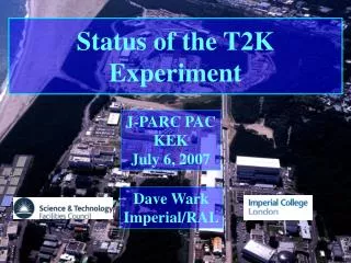
Technical Details of the T2K Horns L. Bartoszek BARTOSZEK ENGINEERING NBI2006
My part in T2K • I have been working with Ichikawa-san and the KEK group on horns 1 and 3 • I model the design in 3D (with much iteration with KEK group,) and Toshiba builds it • I am also working with Eric Zimmerman at CU to design and build horn 2 • Horn 2 is just now ramping up in effort
To be covered here: • Electrically isolated support that absorbs thermal expansion of the horn • Details of stripline connections • Design of a water connection between Stainless and Aluminum that prevents galvanic corrosion • FSW welding in the US • We might use this on horn 2
Electrically isolated support • Ceramic block electrically isolates the horn attachment to its support frame • The upstream end is fixed in X,Y and Z (beam direction) with a pinned joint that allows rotation • The downstream pin joint translates in Z as horn changes temperature
US pin joint DS pin joint
Ceramic disks clamped by threaded rods restrain Lorentz forces on stripline
Clamp for 4 plates just below the remote disconnect showing the larger gap
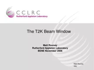
Isolated water connection to Outer Conductor that prevents SS/AL galvanic corrosion
Horn 3 water system Drain lines Supply lines
Elevation view of Horn 3 beam Drain tank
Supply lines Welded bellows with ceramic isolation Auxilliary drain lines
Water spray nozzle ceramic Aux drain fitting Stainless flange Flange to connect nozzles to Outer Conductor supply fitting
EVAC NW25 Al seal between ceramic and horn Al Exploded view of connection Tapping is done in SS flange and Al outer conductor, only counterbores in ceramic Helicoflex SS seal between SS and ceramic
Cutaway Exploded view showing water routing channels in flange
FSW welding • Friction Stir welding produces welds with higher fatigue strength than TIG welding • The Japanese are ahead of the US in commercializing the Friction Stir Welding process • Friction Stir Link, Inc, a new company in WI offers robotic FSW for tube welding • This is great news for the horn 2 effort! • Now we have an alternative to welding at FNAL
Exit point of FSW tool Entry point of FSW tool on test weld