Segmentation and Readout Architecture of the TPC Detector at CERN
This document elaborates on the segmentation of the readout plane in the Time Projection Chamber (TPC) detector, detailing its structure consisting of 18 trapezoidal sectors, each with specified dimensions and operational parameters. The inner chamber features 5504 pads, while the outer chamber has 10332 pads. Various subsystems, including low voltage power supply, data processing, and monitoring are described, along with the cooling mechanisms of the Front End Cards (FECs) and detailed parameters for real-time status and error monitoring. Contributions by Luciano Musa from CERN are highlighted.

Segmentation and Readout Architecture of the TPC Detector at CERN
E N D
Presentation Transcript
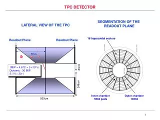
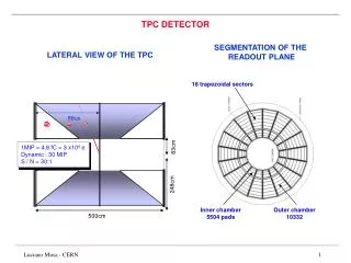
SEGMENTATION OF THE READOUT PLANE 18 trapezoidal sectors 83cm 248cm 88us 500cm Inner chamber 5504 pads Outer chamber 10332 TPC DETECTOR LATERAL VIEW OF THE TPC 1MIP = 4.8 fC = 3 x10⁴ e Dynamic : 30 MIP S / N = 30:1 Luciano Musa - CERN
SIDE VIEW FRONT VIEW 36 trapezoidal sectors Capton Cable C6 : 20 FECs Outer chamber C5 : 20 FECs C4 : 20 FECs FEC 190mm C3 : 18 FECs C2 : 25 FECs 140mm Inner chamber C1 : 18 FECs 128 channels Front End Card (FEC) TPC FEE: MOUNTING Luciano Musa - CERN
FEC 128 ch FEC 128 ch FEC 128 ch FEC 128 ch FEC COOLING CONF. & R/O MON. & CTRL TRIGGER INT (TTC-RX) FEE ARCHITECTURE GLOBAL ARCHITECTURE Each TPC Sector is served by 6 Readout Subsystems 1 LOW VOLTAGE POWER SUPPLY UX CRX 2 CONFIG. & READOUT NETWORK (100 MB / s) DATA PROC. DATA MEMORY DAQ INT (DDL-SIU) DCS NETWORK DCS INT (PROFIB, ETHER, ...) 25 BOARD CONTROLLER RCU Overall TPC: 4356 Front End Card 216 Readout Control Unit Luciano Musa - CERN
FEC COOLING FRONT-END CARD 128-CHANNEL FRONT-END CARD LV SUPPLY readout bus connectors control bus connector power supply connector cooling pipe voltage regulators GTL transceivers (back side) current monitoring & supervision ALTROs Shaping Amplifiers Kapton cables to TPC Luciano Musa - CERN
FRONT_END CARD FEE PARAMETERS TO BE MONITORED AND/OR CONTROLLED (PRELIMINARY !) • Front End Card (FEC) • Temperature: 1 value (10 bits) / FEC R • Volt. Reg. State (on/off): 8 values (8 bits) / FEC R/W • Power Switches (on/off): 2 values (2 bits) / FEC R/W • Analogue Voltage: 1 value (10 bits) / FEC R • Digital Voltage: 1 value (10 bits) / FEC R • Status / Error Register: 1 value (64 bits) / FEC R/W • Readout Control Unit (RCU • Volt. Reg. State (on/off): 4 values (8 bits) / FEC R/W • Power Switches (on/off): 1 values (2 bits) / FEC R/W • Digital Voltages: 2 value (20 bits) / FEC R • Status / Error Register: 1 value (64 bits) / FEC R/W • Events that could damage the FEE components are hardware protected. • The FEE cooling and LV POWER SUPPLY have their independent set of sensors. Luciano Musa - CERN