Download
1 / 16
160 likes | 271 Vues
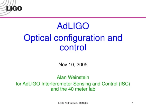
AdLIGO Optical configuration and control Nov 10, 2005 Alan Weinstein for AdLIGO Interferometer Sensing and Control (ISC) and the 40 meter lab. 40 KG FUSED SILICA. AdLIGO optical configuration and control.

E N D
AdLIGO Optical configuration and control Nov 10, 2005 Alan Weinstein for AdLIGO Interferometer Sensing and Control (ISC)and the 40 meter lab LIGO NSF review, 11/10/05
40 KG FUSED SILICA AdLIGO optical configuration and control • Problem: If the current Initial LIGO optical configuration (power-recycled Michelson with Fabry-Perot arms) is retained in AdLIGO, the increased laser power (needed for better sensitivity in the high-frequency shot-noise-limited regime) will put intolerable thermal load on the transmissive (absorptive, lossy) optics in the power recycling cavity (BS, ITM substrates). • Solution: increase the finesse (optical gain) of the F-P arms, decrease the gain in the PRC. ADVANCED LIGO LAYOUT BS Beam Splitter ITM Input Test Mass ETM End Test Mass PD Photodiode PRM Power Recycling Mirror SRM Signal Recycling Mirror LIGO NSF review, 11/10/05
Advanced LIGO optical configuration • Problem: Increasing the finesse of the arms causes the cavity pole frequency to decrease, leading to reduced bandwidth for GW signal. • Solution: resonant sideband subtraction! • the PRM acts to increase the optical gain of the arms, for the carrier. • the SEM acts to decrease the optical gain of the arms, for the GW signal sidebands – the signal sidebands are resonantly extracted out the asymmetric port. • This decouples the problem of storing the carrier power (CARM+PRC) from extracting the signal (DARM+SEC), allowing us to optimize both for best quantum-limited response to signal, and apportionmentof optical gain / thermal load. FP cavity Power PRM Laser FP cavity BS GW signal Detuning SEM LIGO NSF review, 11/10/05
f = 2kls = 4pls(fcarr+fsig)/c rCC rITM RSE tuned (narrow band) RSE SR SR The red curve corresponds to r = rITM, ie, no SR mirror Tuning the signal response • Better solution: Detuned signal extraction optimizes the signal extraction for a signal frequency away from DC, allowing us to resonantly enhance the response at, say, 40 Hz, shaping the frequency response to optimize sensitivity in the presence of other noise sources (thermal, seismic.. which are overwhelming near DC). • By choosing the phase advance of the signal (fcarr+fsig) in the signal recycling cavity, can get longer (SR) or shorter (RSE) storage of the signal in the arms: LIGO NSF review, 11/10/05
Using DR to optimize sensitivity Now we can independently tune hDC and fpolarm to optimize sensitivity (eg, hug the thermal noise curve) LIGO NSF review, 11/10/05
Projected Adv LIGO Detector Performance 10-21 • Newtonian background,estimate for LIGO sites • Seismic ‘cutoff’ at 10 Hz • Suspension thermal noise • Test mass thermal noise • Unified quantum noise dominates at most frequencies for fullpower, broadband tuning Optimize detuned RSE response, in the presence of other noise sources, to maximize BNS range. Initial LIGO 10-22 Strain Advanced LIGO 10-23 10-24 10 Hz 100 Hz 1 kHz LIGO NSF review, 11/10/05
Control of the AdLIGO optical configuration • Problem: the detuned signal extraction, on top of the power-recycled Michelson with Fabry-Perot arms, is a very complicated optical configuration. The current Initial LIGO sensing scheme has no hope of acquiring lock and controlling the mirrors in AdLIGO. • The Initial LIGO scheme uses one pair of RF sidebands for PDH reflection locking of the arms and PRC, and Schnupp transmission locking for the Michelson. The signals for the short degrees of freedom (PRC and MICH) would be overwhelmed by the large signals from the arms, if the arms weren’t tightly controlled: gain hierarchy. • Solution: enhance the length signal extraction by using two pairs of RF sidebands, used in clever ways. • The signals for the short degrees of freedom (PRC, MICH and SEC) can be completely decoupled from the large signals from the arms; the length sensing matrix is much more diagonal, no gain hierarchy needed. Expect control to be more robust! LIGO NSF review, 11/10/05
Carrier (Resonant on arms) -f2 -f1 f1 f2 AdLIGO signal extraction scheme ETMy • Mach-Zehnder installed to eliminate sidebands of sidebands. • Only + f2is resonant on SRC. • Unbalanced sidebands of +/-f2 due to detuned SRC produce good error signal for Central part. • Arm cavity signals are extracted from beat between carrier and f1 or f2. • Central part (Michelson, PRC, SRC) signals are extracted from beat between f1 and f2, not including arm cavity information. 4km f2 ITMy ETMx PRM ITMx BS 4km f1 SRM • Single demodulation • Arm information • Double demodulation • Central part information LIGO NSF review, 11/10/05
5 DOF for length control Signal Extraction Matrix (in-lock) ETMy Phase Modulation f1=33MHz f2=166MHz Ly=38.55m Finesse=1235 ITMy Common of arms Differential of arms Power recycling cavity Michelson Signal recycling cavity : L=(Lx Ly) / 2 : L=Lx Ly : l=(lx ly) / 2 =2.257m : l=lx ly = 0.451m : ls=( lsx lsy) / 2 =2.15m GPR=14.5 lsy ETMx Laser ly ITMx BS lx Lx =38.55m Finesse=1235 PRM lsx T=7% SRM T=7% PO SP AP LIGO NSF review, 11/10/05
Full lock of AdLIGO optical configuration at the 40 Meter prototype • Problem: this is all fine in theory, but does it work in practice? • Apparently so! We can use this scheme to acquire lock and control the 40m prototype interferometer, even during the noisy daytime. • Full lock acquisition is now relatively routine, and robust. • The optical response is precisely as expected, including the resonant enhancement (at the 40m, this is at 4 kHz; in AdLIGO, it will be at ~40 Hz) as well as the optical spring (in the 40m, at ~50 Hz). • In the process, we have learned a great deal about the intricacy of the AdLIGO optical design, and how to control it. • Exploiting the enhanced controls and more diagonal sensing matrix, we are developing deterministic lock acquisition procedures, step-by-step approaches to take the wait and chance out of lock acquisition. LIGO NSF review, 11/10/05
ETMy Shutter ITMy PRM ETMx ITMx Carrier 33MHz 166MHz BS Shutter SRM The path to full RSE at the 40m Oct. 2004 Detuned dual recycled Michelson Oct. 2005 RSE Nov. 2004 Arm lock with offset in common mode Reducing offset LIGO NSF review, 11/10/05
Frequency sweep of optical spring ~1900W ~270W LIGO NSF review, 11/10/05
Optical spring and Optical resonance in differential arm mode of detuned RSE • Optical gain of L- loop • DARM_IN1/DARM_OUT divided by pendulum transfer function • Optical spring and optical resonance of detuned RSE were measured. • Frequency of optical spring depends on cavity power, mass, detuning phase of SRC. • Frequency of optical resonance depends on detuning phase of SRC. • Theoretical line was calculated using A. Buonanno and Y.Chen’s equations. LIGO NSF review, 11/10/05
Optical spring in E2E • Calculated by time domain simulation • No length control • Lock lasts ~0.7sec, so statistics at low frequency is not good. • Simple length control required • Calculation time ~5min using DRMI summation cavity LIGO NSF review, 11/10/05
But will it work in AdLIGO? • AdLIGO has • 4 km arms (longer storage time) • quadruple pendulums (much quieter, but also much less actuation force on the test mass) • advanced seismic isolation (much quieter) • No problems are foreseen, but we must extrapolate from 40m to AdLIGO with detailed simulation -> e2e. • Will maintaining lock be more difficult in Adv LIGO? We might expect it will be significantly easier, because of the much quieter seismic platform, powerful multiple pendulum isolation, and more diagonal length sensing plant. • This is an inference that must be verified through tests (LASTI) and simulation (e2e). LIGO NSF review, 11/10/05
Differences betweenAdvLIGO and 40m prototype • 100 times shorter cavity length • Arm cavity finesse at 40m chosen to be = to AdvLIGO ( = 1235 ) • Storage time is x100 shorter • Control RF sidebands are 33/166 MHz instead of 9/180 MHz • Due to shorter PRC length, less signal separation • LIGO-I 10-watt laser, negligible thermal effects • 180W laser will be used in AdvLIGO. • Noisier seismic environment in town, smaller isolation stacks • ~1x10⁻⁶m at 1Hz • LIGO-I single pendulum suspensions • AdvLIGO will use triple (MC, BS, PRM, SRM) and quad (ITMs, ETMs) suspensions. LIGO NSF review, 11/10/05