Download
1 / 53
530 likes | 564 Vues
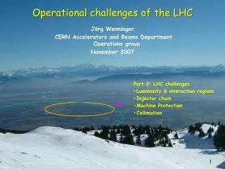
Operational challenges of the LHC. J örg Wenninger CERN Accelerators and Beams Department Operations group November 2007. Part 2: LHC challenges Luminosity & interaction regions Injector chain Machine Protection Collimation. Luminosity and Interaction Regions.

E N D
Operational challenges of the LHC JörgWenninger CERN Accelerators and Beams Department Operations group November 2007 • Part 2: LHC challenges • Luminosity & interaction regions • Injector chain • Machine Protection • Collimation
Luminosity & its limitations • The equation for luminosity reveals different parameters that can be tuned to maximize L: • f : the revolution frequency is given by the circumference, f=11.246 kHz. • N : the bunch population – N=1.15x10¹¹ protons • - Injectors (brighter beams) • - Collective interactions of the particles • - Beam encounters • k : the number of bunches – k=2808 • - Injectors (more beam) • - Collective interactions of the particles • - Interaction regions • - Beam encounters • s* : the size at the collision point –s*y=s*x=16 mm • - Injectors (brighter beams) • - More focusing – stronger quadrupoles For k = 1:
Collective (in-)stability • The electromagnetic field of a bunch interacts with the chamber walls (finite resistivity !), cavities, discontinuities etc that it encounters: • The fields act back on the bunch itself or on following bunches. • Since the fields induced by of a bunch increase with bunch intensity, the bunches may become COLLECTIVELY unstable beyond a certain intensity, leading to poor lifetime or massive looses intensity loss. • Such effects can be very strong in the LHC injectors, and they will affect the LHC: we have many carbon collimators that have a bad influence on beam stability! • With the presently installed collimators, we cannot reach nominal performance because of beam (in)stability !!
Electron clouds… • … affect intense beams with positive charge and closely spaced bunches. • Electrons are generated at the vacuum chamber surface by beam impact, photons… • If the probability to emit secondary e- is high enough, more e- are produced and accelerated by the field of a following bunch(es) and multiplication start… • The cloud of e- that may build up can drive the beam unstable, and at the LHC, overload the cryogenic system by the heat they deposit on the chamber walls ! • This effect depends strongly on surface conditions, simulations are tricky because they are very sensitive to very low energy (~ eV) electrons. The latest simulation indicate that the problem may be less severe than initially anticipated but … • Fortunately the impact of all those electrons cleans the chamber surface, reduces the electron emission probability and eventually the cloud disappears ! Bunch N+2 accelerates the e-, more multiplication… Bunch N+1 accelerates the e-, multiplication at impact Bunch N liberates an e- e- e- N+2 N+1 N ++++++ ++++++ ++++++ e-
Electron Cloud Detectors • When first beams with LHC structure and intensity were injected into the SPS, the beam was completely unstable and within seconds the vacuum valves closed due to high pressure ! • The origin of the problem was traced to electron clouds, and since then the SPS has become an electron cloud ‘laboratory’, in particular to study the surface cleaning by the cloud itself. • The electron clouds have been studied using for example dedicated Si-strip detectors installed inside the vacuum chamber. Collecting stripsBeam “pipe” (< 30 K)
Electron Cloud Measurements at SPS Intensity 3 bunch groups The cloud grows with the number of closely spaced bunches: each bunch amplifies the cloud (until it saturates) Longitudinal position in ring Injection an LHC beam at 26 GeV: up to 3 groups of 72 bunches at intervals of 3.6 seconds No. e- Time (ms) Transverse position (mm) wrt center of vacuum chamber
‘Beam-beam’ interaction • When a particle of one beam encounters the opposing beam at the collision point, it senses the fields of the opposing beam. • Due to the typically Gaussian shape of the beams in the transverse direction, the field (force) on this particle is non-linear, in particular at large amplitudes ! • The effect of the non-linear fields can become so strong (when the beams are intense) that large amplitude particles become unstable and are lost from the machine: • poor lifetime • background • THE INTERACTION OF THE BEAMS SETS A LIMIT ON THE BUNCH INTENSITY! Quadrupole lens Beam(-beam) lens
Beam envelope CMS collision point ARC cells ARC cells Fits through the hole of a needle! • The envelope of the size beam is given by the so-called ‘b’-function ( optics): • In the arcs the optics follows a regular pattern. • In the long straight sections, the optics is matched to the ‘telescope’ that provides very strong focusing at the collision point. • Collision point size (rms, defined by ‘b*’): • CMS & ATLAS : 16 mm LHCb : 22 – 160 mm ALICE :16 mm (ions) / >160 mm (p)
Combining the beams for collisions • The 2 LHC beams circulate in separate vacuum chambers in most of the ring, but they must be brought together to collide. • Over a distance of about 260 m, the beams circulate in the same vacuum chamber and they are a total of ~ 120 encounters in ATLAS, CMS, ALICE and LHCb.
Interaction region layout 46 m • The final focus is made with the high gradient and large aperture ‘triplet’ quadrupoles (US-JAPAN) : • - Large beam size ~ 100 x size at IP • - Large beam separation from crossing angle ~ 12 mm • Beam sizes : • at IP (ATLAS, CMS) s = 16 mm b* = 0.5 m • in the triplets s = ~1.6 mm b ~ 5’000 m • in the arcs s = ~0.2 mm b = 200 m s b
IP Crossing angles • Since every collision adds to the ‘Beam-beam budget’ un-necessary direct beam encounters must be avoided wherever the beams share a common vacuum: • COLLIDE WITH A CROSSING ANGLE IN ONE PLANE ! • There is a price to pay : • A reduction of the luminosity due to the finite bunch length of 7.6 cm and the non-head on collisions L reduction of ~ 17%. • Crossing planes & angles • ATLAS Vertical 280 mrad • CMS Horizontal 280 mrad • LHCb Horizontal 300 mrad • ALICE Vertical 400 mrad 7.5 m
Tevatron • The TEVATRON is presently the ‘energy frontier’ collider in operation at FNAL, with a beam energy of 980 GeV and a size of ~ ¼ LHC. • It is the first super-conducting collider ever build. • It collides proton and anti-proton bunches that circulate in opposite directions in the SAME vacuum chamber. • The TEVATRON has undergone a number of remarkable upgrades and it presently collides 36 proton with 36 anti-proton bunches (k=36), with bunch populations (N) similar to the ones of the LHC (but there are always fewer anti-protons !). • One of the problems at the TEVATRON are the long-distance encounters of the bunches in the arc sections. A complicated separation scheme with electrostatic elements has to be used: Luminosity gain of LHC comes basically from k !! Tricky to operate !! E E
The LHC injector complex • The CERN Proton Injectors: • Linac 2 (1979) • Proton Synchrotron Booster (4 superposed rings !) - PSB (1972) • Proton Synchrotron – PS (1959) • Super Proton Synchrotron – SPS (1976) • The PSB-PS-SPS Complex had to be upgraded in order to provide the beams with the appropriate intensity, pattern (25 ns spacing) and size for the LHC ! • Two 3 km long new transfer lines had to be build to transfer the 450 GeV SPS beam to the LHC. • Latest items that have been commissioned, both October/November 2007 : • - The transfer line for the injection into ring 1 (injected in IR2/ALICE). • The lead ion beam in the SPS: accelerated to 450 GeV and extracted into the transfer line to the LHC. • The injectors have a delicate task, because protons (and ions) ‘remember’ everything you do to them – in particular the harmful things that increase the beam size !
Beam 2 5 LHC 6 4 Beam 1 7 3 TI8 SPS 2 8 TI2 Booster 1 protons LINACS Top energy/GeVCircumference/m Linac 0.12 30 PSB 1.4 157 CPS 26 628 = 4 PSB SPS 450 6’911 = 11 x PS LHC 7000 26’657 = 27/7 x SPS CPS Ions LEIR Note the energy gain/machine of 10 to 20 – and not more ! The gain is typical for the useful range of magnets !!!
LHC beam injection (and extraction) Circulating beam Kicker B-field Injected beam Injected beam Septum magnet B B time Kicker magnet Circulating beam Kicker magnet • A septum dipole magnet (with thin coil) is used to bring the injected beam close to the circulating beam. • A fast pulsing dipole magnet (‘kicker’) is fired synchronously with the arrival of the injected beam: deflects the injected beam onto the circulating beam path. • ‘Stack’ the injected beams one behind the other. • At the LHC the septum deflects in the horizontal plane, the kicker in the vertical plane (to fit to the geometry of the tunnels). • Extraction is identical, but the process is reversed !
Bunch patterns The nominal bunch pattern of the LHC is created by combining and splitting of bunches in the injector chain : 6 booster bunches are injected into the PS. Each of the 6 bunches are split into 12 smaller bunches in the PS, yielding a total of 72 bunches at extraction from the PS. Between 2 and 4 batches of 72 bunches are injected into the SPS, yielding between 144 and 288 bunches at extraction from the SPS. A sequence of 12 extraction of 144 to 288 bunches from the SPS are injected into the LHC.
Bunch Splitting at the PS • The bunch splitting in the PS machine is the most delicate operation that is performed in the injector chain. • The quality of the splitting is critical for the LHC (uniform intensity in all bunches…).
Bunch pattern details • The nominal LHC pattern consists of 39 groups of 72 bunches (spaced by 25 ns), with variable spacing between the groups to accommodate the rise times of the fast injection and extraction magnets (‘kickers’). • There is a long 3 ms hole (t5)for the LHC dump kicker (see later). 72 bunches t5 t3 t2 t1
The price of high fields & high luminosity… • When the LHC is operated at 7 TeV with its design luminosity & intensity, • the LHC magnets store a huge amount of energy in their magnetic fields: • per dipole magnet Estored = 7 MJ • all magnets Estored = 10.4 GJ • the 2808 LHC bunches store a large amount of kinetic energy: • Ebunch = N x E = 1.15 x 1011 x 7 TeV = 129 kJ • Ebeam = k x Ebunch = 2808 x Ebunch= 362 MJ • To ensure safe operation (i.e. without damage) we must be able to dispose of all that energy safely ! • This is the role of Machine Protection !
Stored Energy • Increase with respect to existing accelerators : • A factor 2 in magnetic field • A factor 7 in beam energy • A factor 200 in stored energy
DFB Cryostat HTS Current Leads Power Converter Powering superconducting magnets • The magnet is cooled down to 1.9K or 4.5K • Installed in a cryostat. • The magnet must be powered • Room temperatur power converters supply the current. • The magnet must be connected • By superconducting cables inside the cryostat. • By normal conducting cables outside the cryostat. • The superconducting cables must be connected to normal conducting cables • Connection via current leads inside special cryostat (DFB)
LHC powering in sectors • To limit the stored energy within one electrical circuit, the LHC is powered by sectors. • The main dipole circuits are split into 8 sectors to bring down the stored energy to ~1 GJ/sector. • Each main sector (~2.9 km) includes 154 dipole magnets (powered by a single power converter) and ~50 quadrupoles. • This also facilitates the commissioning that can be done sector by sector ! 5 4 6 DC Power feed LHC 7 3 DC Power 27 km Circumference Powering Sector 8 2 1 Sector
Powering from room temperature source… 6 kA power converter Water cooled 13 kA Copper cables ! Not superconducting !
…to the cryostat Feedboxes (‘DFB’) : transition from Copper cable to super-conductor Cooled Cu cables
Quench • A quench is the phase transition from the super-conducting to a normal conducting state. • Quenches are initiated by an energy in the order of few mJ • Movement of the superconductor by several m (friction and heat dissipation). • Beam losses. • Cooling failures. • ... • When part of a magnet quenches, the conductor becomes resistive, which can lead to excessive local energy deposition (temperature rise !!) due to the appearance of Ohmic losses. To protect the magnet: • The quench must be detected: a voltage appears over the coil (R ~ 0 to R > 0). • The energy release is distributed over the entire magnet by force-quenching the coils using quench heaters (such that the entire magnet quenches !). • The magnet current has to be switched off within << 1 second.
Quench - discharge of the energy Power Converter Discharge resistor Magnet 1 Magnet 2 Magnet 154 Magnet i • Protection of the magnet after a quench: • The quench is detected by measuring the voltage increase over coil. • The energy is distributed in the magnet by force-quenching using quench heaters. • The current in the quenched magnet decays in < 200 ms. • The current of all other magnets flows through the bypass diode (triggered by the voltage increase over the magnet) that can stand the current for 100-200 s. • The current of all other magnets is dischared into the dump resistors.
Dump resistors Those large air-cooled resistors can absorb the 1 GJ stored in the dipole magnets (they heat up to few hundred degrees Celsius).
If it does not work… During magnet testing the 7 MJ stored in one magnet were released into one spot of the coil (inter-turn short) P.Pugnat
Beam induced damage test The effect of a high intensity beam impacting on equipment is not so easy to evaluate, in particular when you are looking for damage : heating, melting, vaporization … • Controlled experiment: • Special target (sandwich of Tin, Steel, Copper plates) installed in an SPS transfer line. • Impact of 450 GeV LHC beam (beam size σx/y ~ 1 mm) Beam 25 cm
Damage potential of high energy beams • Controlled experiment with 450 GeV beam to benchmark simulations: • Melting point of Copper is reached for an impact of 2.5×10¹² p, damage at 5×10¹² p. • Stainless steel is not damaged with 7×10¹² p. • Results agree with simulation. • Effect of beam impact depends strongly on impact angles, beam size… A B D C Based on those results LHC has a limit for safe beam at 450 GeV of 1012 protons ~ 0.3% of the total intensity Scaling the results yields a limit @ 7 TeVof 1010 protons ~ 0.003% of the total intensity Safe beam = No damage !
vaporisation melting Full LHC beam deflected into copper target Copper target 2808 bunches 2 m Energy density [GeV/cm3] on target axis Target length [cm] The beam will drill a hole along the target axis !!
Schematic layout of beam dump system in IR6 When it is time to get rid of the beams (also in case of emergency!) , the beams are ‘kicked’ out of the ring by a system of kicker magnets and send into a dump block ! Septum magnets deflect the extracted beam vertically Beam 1 Kicker magnets to paint (dilute) the beam Q5L Beam dump block Q4L about 700 m 15 fast ‘kicker’ magnets deflect the beam to the outside Q4R about 500 m Q5R quadrupoles Beam 2
The dump block • This is the ONLY element in the LHC that can withstand the impact of the full beam ! • The block is made of graphite (low Z material) to spread out the hadronic showers over a large volume. • It is actually necessary to paint the beam over the surface to keep the peak energy densities at a tolerable level ! beam absorber (graphite) Approx. 8 m concrete shielding
Beam on dump block • To reduce the peak energy density in the dump block : • Beam size is increased to ~1 mm due to long distance from ring to the dump block. • Additional blow up due to dilution kickers: painting of beam on beam dump block. • Note : the beam impacts over less than 0.1 ms.
…takes shape ! CERN visit McEwen 38
‘Unscheduled’ beam loss due to failures In the event a failureor unacceptable beam lifetime, the beammust bedumpedimmediately and safely into thebeam dump block Two main classes for failures (with more subtle sub-classes): • Passive protection • - Failure prevention (high reliability systems). • Intercept beam with collimators and absorber blocks. • Active protection systems have no time to react ! Beam loss over a single turn during injection, beam dump or any other fast ‘kick’. Active Protection - Failure detection (by beam and/or equipment monitoring) with fast reaction time (< 1 ms). - Fire beam dumping system Beam loss over multiple turns due to many types of failures.
LHC Devices LHC Devices LHC Devices Movable Devices BCM Beam Loss Experimental Magnets Collimator Positions Environmental parameters BTV screens Mirrors Safe Mach. Param. Software Interlocks SEQ CCC Operator Buttons Experiments Transverse Feedback Beam Aperture Kickers Collimation System FBCM Lifetime BTV PIC essential + auxiliary circuits WIC FMCM BLM Access System Vacuum System RF System BPM in IR6 Monitors in arcs (several 1000) Monitors aperture limits (some 100) Magnets Power Converters Doors EIS Vacuum valves Access Safety Blocks RF Stoppers QPS (several 1000) Power Converters ~1500 AUG UPS Cryo OK Interlock system Over 10’000 signals enter the interlock system of the LHC !! Timing Beam Dumping System Beam Interlock System Safe Beam Flag Injection BIS Timing System (Post Mortem)
Example : beam loss monitors • Ionization chambers to detect beam losses: • N2 gas filling at 100 mbar over-pressure, voltage 1.5 kV • Sensitive volume 1.5 l • Reaction time ~ ½ turn (40 ms) • Very large dynamic range (> 106) • There are ~3600 chambers distributed over the ring to detect abnormal beam losses and if necessary trigger a beam abort !
Operational margin of SC magnet The LHC is ~1000 times more critical than TEVATRON, HERA, RHIC Applied Field [T] Bccritical field Bc quench with fast loss of ~106-7 protons 8.3 T / 7 TeV QUENCH Tccritical temperature quench with fast loss of ~1010 protons Tc 0.54 T / 450 GeV 1.9 K 9 K Temperature [K]
Beam lifetime • Consider a beam with a lifetime t : • Number of protons lost per second for different lifetimes (nominal intensity): • t = 100 hours ~ 109 p/s • t = 25 hours ~ 4x10⁹ p/s • t = 1 hour ~ 1011 p/s • While ‘normal’ lifetimes will be in the range of 10-100 hours (in collisions most of the protons are actually lost in the experiments !!), one has to anticipate short periods of low lifetimes. • To survive periods of low lifetime (down to 0.2 hours) we must intercept the protons that are lost with very very high efficiency before they can quench a superconducting magnet : collimation! Quench level ~ 106-7 p
Beam collimation • A multi-stage halo cleaning (collimation) system has been designed to protect the sensitive LHC magnets from beam induced quenches : • Halo particles are first scattered by the primary collimator (closest to the beam). • The scattered particles (forming the secondary halo) are absorbed by the secondary collimators, or scattered to form the tertiary halo. • More than 100 collimators jaws are needed for the nominal LHC beam. • Primary and secondary collimators are made of Carbon to survive severe beam impacts ! • The collimators must be very precisely aligned (< 0.1 mm) to guarantee a high efficiency above 99.9% at nominal intensities. • the collimators will have a strong influence on detector backgrounds !! Experiment Protection devices Primary collimator Secondary collimators Tertiary collimators Triplet magnets Absorbers Tertiary halo hadronic showers Primary halo particle Secondary halo + hadronic showers Beam It’s not easy to stop 7 TeV protons !!
Collimator settings at 7 TeV • For colliders like HERA, TEVATRON, RHIC, LEP collimators are/were used to reduce backgrounds in the experiments ! But the machines can/could actually operate without collimators ! • At the LHC collimators are essential for machine operation as soon as we have more than a few % of the nominal beam intensity ! The collimator opening corresponds roughly to the size of Spain ! 1 mm Opening ~3-5 mm
‘Phase 1Collimator’ Designed for highest robustness. Carbon Composite material for the jaws that are with water cooled. Drawback : not ‘ideal’ for beam stability ! >> Second generation collimator with metal coated surfaces..
RF contacts for guiding image currents Beam spot
The LHC machine cycle collisions beam dump energy ramp collisions 7 TeV start of the ramp Squeeze injection phase preparation and access 450 GeV