Prototyping and Testing of the CLAS12 Forward Detector PCAL Component
This report outlines the design, testing, and prototyping of the Photon Imaging Calorimeter (PCAL) for the CLAS12 Forward Detector. It focuses on achieving optimal geometric coverage and good resolution for photons and electrons up to 10 GeV, with enhanced particle identification capabilities for improved event reconstruction. Emphasizing mechanical engineering aspects, the document discusses the component's compatibility with existing structures and testing methods for operational parameters, while detailing results on position and energy resolutions, as well as light yield from various photomultiplier tubes.

Prototyping and Testing of the CLAS12 Forward Detector PCAL Component
E N D
Presentation Transcript
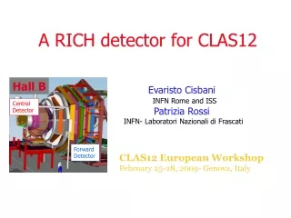
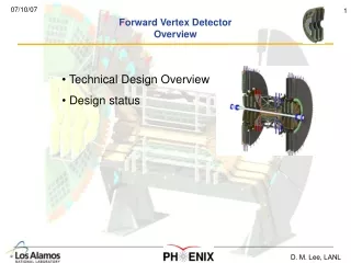
CLAS12 Forward Detector Element PCAL Component Testing & Prototyping • K. Giovanetti (JMU) • Collaborating Institutions: • YerPhI (G. Asryan, H Voskanyan), • JLab,JMU, OU, NSU, Orsay-IPN
Design Requirement Review • Comparable geometric coverage for PCAL with respect to the EC, • Good resolution/calorimetry up to 10 GeV photons and electrons • Improved particle identification ability to enhance final state reconstruction, • Information on the longitudinal shower development (5, 5, 8) • Fast calorimeter response for use the Level 1 trigger (100 ns), • Reasonable Timing (1 ns) • Sufficient position information to resolve • Event reconstruction derived from component properties and the readout information, • Compatibility with the present EC and other CLAS components. • Mechanical engineering considerations: support, compatibility, structures (D. Kashy), • Constructability (reasonable facilities, manpower and resources to assemble detectors) • Reasonable options for testing components to establish PCAL operational parameters,
EC Achieved • Position Resolution 2-3 cm • Energy Resolution (10-12)%/√E • PE Yield 3.4 pe/MeV • Time Resolution < 0.5 ns DESIGN GOALS
PCAL Design • Alternating Pb (2.2mm)/Scintillator (10 mm) • Scintillator Width • 4.5 cm • 9cm [double width readout] • U,V,W Readout • Cover the EC ~4m Sides • WLS Light Readout • 3 fibers
Components Tested Photomultiplier Tubes Type Of WLS Fiber Number Of Fibers/ Scint. Type Of Scintillator
Test Setup (In The EEL) 4 m long dark box with moving cart and support fixtures (Hall B engineering) Simple DAQ (CODA) – FASTBUS with LeCroy ADC Test Scintillator with Groove(s) FNAL, Kharkov, ELJEN Trigger PMT XP2262 Rad.Sources: 90Sr and 207Bi Cosmic muons Second Trigger PMT Test WS fibers Y11(sc-1, 1.5, 2; mc-1 (mm)) BC-91A, BC-92 (1mm) Test PMTs R7899, R6095, R1450 XP1912, XP2802 9224B
Fits To ADC Distributions Hamamatsu R7899EG, Green Sensitive Photocathode Fit to the pedestal and single photoelectron peak FNAL Scintillator With One Grove, Kuraray Y-11 Single Clad Fiber Fit to the pedestal and single photoelectron peak Hamamatsu R6095, 15% QE at 500nm
Fit To The ADC Distributions From 90sr For R6095 PMT Of Different HV Fit to Slices of Trigger PMT ADC Distribution FNAL Scintillator with 1 Groove Kuraray 1mm, Single-clad WSF PMT Hamamatsu R6095 Number of photo-electrons 800 V 850 V 900 V ADC Trigger PMT
Fit To The ADC Distributions From 90sr Scintillator Strips With 3-grooves, Kharkov. ADC Distributions Of R6095 For One, Two, And Three Fiber Readout 1 WSF 2 WSF 3 WSF ADC Trigger PMT
Absolute Light Yield With Cosmic Muons FNAL scintillator, 1 cm thick, with 1mm WS fiber, Kuraray Y-11 s.c., PMT Hamamatsu R6095 7-8 photoelectrons 2 MeV Second trigger counter
Summary of test measurements • Best PMT is the HAMAMATSU R7899EG, $280/each. • HAMAMATSU R6095 [selected with QE>16% at 500nm] • Photoelectron yield 25% lower. • R6095 is $160 ($180 gain spec). • Other PMTs did not perform better and are expensive, >$250 • Multi-clad fiber • 20% more light vs single-clad fiber • 30% more expensive • FNAL extruded scintillator with Y-11 fiber has the best light yield, • price, $20-$25/meter. • Kharkov are close, need R&D to match the FNAL performance.
Component Recommendation The best combination by the light yield and price is: FNAL scintillator Kuraray Y11 single clad HAMAMATSU R6095. Light yield ~11p.e./MeV (3 fibers)
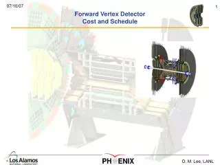
Prototype: Box-Prototype • Small dimensions = on order of 30 cm • Full longitudinal structure (5 modules) • Mimic UVW readout • Beam tests • Shower characterization • Complete component combined response • Explore fiber routing & PMT mounting
Pre-shower Prototype (Side View) WSF (KURARAY 1mm, SC) FNAL scintilliator strip 45X10mm , 3 grooves 2 Lead 2.2mm
Box-Prototype: WLS Fiber/ Scintillator Prototype Assembly Fibers are glued in the grooves of FNAL scintillator. This will be the active medium for the sampling calorimeter.
Box-Prototype: Aligning Scintillator Prototype Assembly The scintillators are then placed in a supporting structure which holds the scintillator in place while allowing the fiber to be routed to the exterior.
Box-Prototype: Fiber Routing Prototype Assembly The photomultipliers will be mounted along the sides. Each of three sides will have fiber channels to the exterior in order to obtain a three view readout.
Prototype: Full Scale • Match Final Dimensions Of PCAL • Explore Construction Methods • Assembly • Component: Storage, Delivery, Alignment • Mechanical Support • Fiber: Handling, Gluing & Routing • Develop Quality Control Measures • Refine Component Testing Methods • Large Dimension Attenuation Lengths
Prototype: Full Scale The large number of photomultipliers, scintillator strips, the significant length of fiber and the length of the longest pieces create challenges that can be best addressed by building at least partially a full scale prototype.
Conclusion • Components That Meet Design Criteria • Small Prototype Under Construction • Significant Advantages Associated With Large Prototype Development
END EXTRA Slides follow
Measurements technique • For each PMT, a single photo-electron peak position and the width, at given HV, was determined using two Gaussian fit to the ADC distributions of attenuated light • For each combination, the average number of photo-electrons was extracted as a function trigger PMT ADC value, the fit function: Fit parameters: c1, c2, c3, and npe
Fit to the ADC distributions from 90Sr for different PMT Fit to slices of trigger PMT ADC distribution R7899 9.1 pe R6095 6.9 pe Number of photo-electrons XP2802 6.7 pe R1450 5.8 pe FNAL scintillator with 1 groove Kuraray 1mm, single-clad WSF ADC Trigger PMT
Fit to the ADC distributions from 90Sr for R6095 PMT at different scintillators Fit to slices of trigger PMT ADC distribution ELJEN 2.2 pe Number of photo-electrons FNAL 6.9 pe Kharkov6.1 pe Kuraray 1mm, single-clad WSF PMT Hamamatsu R6095 ADC Trigger PMT
Fit to the ADC distributions from 90Sr for R6095 PMT of different positions source Fit to slices of trigger PMT ADC distribution Test PMT Kuraray 1mm, SC WSF 90Sr with collimator Number of photo-electrons Kharkov scint. ADC Trigger PMT
Possible Configurations Number of photomultiplier tubes is determined by the segmentation which is is based on the spatial resolution. Improvements in PMT performance do not result in a reduction of the number of photomultiplier tubes. Improvements in the fiber performance could potentially reduce the number of fibers required. This would reduce redundancy (broken fiber) and most likely uniformity. Number of layers was examined in Monte Carlo simulations and the results summarizing these results suggest 15 layers (5 modules) is the best choice.
Configurations with 9, 12, and 15 layers • p0 reconstruction efficiency decreases at high energies for 12 and 9 layer modules • not enough radiator thickness and some of high energy photons do not convert • 12 layers configuration with first 3 layers of lead with double thickness had comparable efficiency but ~10% worse energy resolution 1 module = 3 layers of scintillator-lead
Different Readout Segmentations Simulations with 15 layers of scintillators and 14 layer of lead • Efficiency of reconstruction of two clusters from p0’gg decay decreases for small number of readout segments • For p0 energies up to 10 GeV efficiency of two cluster separation is reasonably high for 4.5 cm wide segmentation
Selection Of The PCAL Components Choice for the scintillator, WLS fiber, and PMT is : Fermi Lab extruded scintillators, 4.5x1 cm2 with 3 grooves Kuraray, 1mm diameter Y11 single clad HAMAMATSU R6095 selected with Q.E.>16% @ 500 nm Expected photo-electron yield ~11p.e./MeV for 3 fibers(yield for EC readout from the test measurements was ~8.4p.e./MeV) Scintillator-WLSF-PMT combination with reasonably high photo-electron statistics at low cost
All single strips U-double V&W-single W-single V-single U-single W-single, U&V-double V-single, U&W-double
Measurements technique • For each PMT, a single photoelectron peak position and the width, at given HV, was determined using two Gaussian fit to the ADC distributions of attenuated light • For each combination, the average number of photo-electrons was extracted as a function trigger PMT ADC value, the fit function: Fit parameters: c1, c2, c3, and npe