Resistance
Resistance. OBJECTIVES. Become familiar with the parameters that determine the resistance of an element and be able to calculate the resistance from the given dimensions and material characteristics.

Resistance
E N D
Presentation Transcript
OBJECTIVES • Become familiar with the parameters that determine the resistance of an element and be able to calculate the resistance from the given dimensions and material characteristics. • Understand the effects of temperature on the resistance of a material and how to calculate the change in resistance with temperature.
OBJECTIVES • Become familiar with the broad range of commercially available resistors available today and how to read the value of each from the color code or labeling.
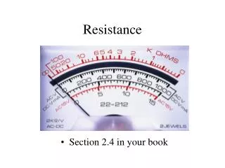
INTRODUCTION • This opposition to the flow of charge through an electrical circuit, called resistance, has the units of ohms and uses the Greek letter omega (Ω) as its symbol. • The graphic symbol for resistance, which resembles the cutting edge of a saw.
FIG. 3.1 Resistance symbol and notation. INTRODUCTION
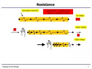
INTRODUCTION • This opposition, due primarily to collisions and friction between the free electrons and other electrons, ions, and atoms in the path of motion, converts the supplied electrical energy into heat that raises the temperature of the electrical component and surrounding medium. • The heat you feel from an electrical heater is simply due to current passing through a high-resistance material.
RESISTANCE • The resistance of any material is due primarily to four factors: • Material • Length • Cross-sectional area • Temperature of the material
RESISTANCE • The atomic structure determines how easily a free electron will pass through a material. • The longer the path through which the free electron must pass, the greater is the resistance factor. • Free electrons pass more easily through conductors with larger crosssectional areas. • In addition, the higher the temperature of the conductive materials, the greater is the internal vibration and motion of the components that make up the atomic structure of the wire, and the more difficult it is for the free electrons to find a path through the material.
RESISTANCE • The first three elements are related by the following basic equation for resistance:
FIG. 3.2 Factors affecting the resistance of a conductor. RESISTANCE
FIG. 3.10 Demonstrating the effect of a positive and a negative temperature coefficient on the resistance of a conductor. TEMPERATURE EFFECTS
TYPES OF RESISTORSFixed Resistors • Resistors are made in many forms, but all belong in either of two groups: fixed or variable. • The most common of the low-wattage, fixedtype resistors is the film resistor.
FIG. 3.12 Film resistors: (a) construction; (b) types. TYPES OF RESISTORSFixed Resistors
FIG. 3.13 Fixed-composition resistors: (a) construction; (b) appearance. TYPES OF RESISTORSFixed Resistors
FIG. 3.14 Fixed metal-oxide resistors of different wattage ratings. TYPES OF RESISTORSFixed Resistors
FIG. 3.15 Various types of fixed resistors. TYPES OF RESISTORSFixed Resistors
TYPES OF RESISTORSVariable Resistors • Variable resistors, as the name implies, have a terminal resistance that can be varied by turning a dial, knob, screw, or whatever seems appropriate for the application. • They can have two or three terminals, but most have three terminals. If the two- or three-terminal device is used as a variable resistor, it is usually referred to as a rheostat.
TYPES OF RESISTORSVariable Resistors • If the three-terminal device is used for controlling potential levels, it is then commonly called a potentiometer. • Even though a three-terminal device can be used as a rheostat or a potentiometer (depending on how it is connected), it is typically called a potentiometer when listed in trade magazines or requested for a particular application.
FIG. 3.16 Potentiometer: (a) symbol; (b) and (c) rheostat connections; (d) rheostat symbol. TYPES OF RESISTORSVariable Resistors
FIG. 3.17 Molded composition-type potentiometer. (Courtesy of Allen-Bradley Co.) TYPES OF RESISTORSVariable Resistors
FIG. 3.18 Resistance components of a potentiometer: (a) between outside terminals; (b) between wiper arm and each outside terminal. TYPES OF RESISTORSVariable Resistors
FIG. 3.19 Variable resistors: (a) 4 mm (5/32 in.) trimmer (courtesy of Bourns, Inc.); (b) conductive plastic and cermet elements (courtesy of Honeywell Clarostat); (c) three-point wire-wound resistor. TYPES OF RESISTORSVariable Resistors
FIG. 3.20 Potentiometer control of voltage levels. TYPES OF RESISTORSVariable Resistors
COLOR CODING AND STANDARD RESISTOR VALUES • A wide variety of resistors, fixed or variable, are large enough to have their resistance in ohms printed on the casing. • Some, however, are too small to have numbers printed on them, so a system of color coding is used. • For the thin-film resistor, four, five, or six bands may be used. • The four-band scheme is described. • Later in this section the purpose of the fifth and sixth bands will be described.
FIG. 3.21 Color coding for fixed resistors. COLOR CODING AND STANDARD RESISTOR VALUES
FIG. 3.22 Color coding. COLOR CODING AND STANDARD RESISTOR VALUES
FIG. 3.23 Example 3.11. FIG. 3.24 Example 3.12. COLOR CODING AND STANDARD RESISTOR VALUES
FIG. 3.25 Five-band color coding for fixed resistors. COLOR CODING AND STANDARD RESISTOR VALUES
TABLE 3.5 Standard values of commercially available resistors. COLOR CODING AND STANDARD RESISTOR VALUES
FIG. 3.26 Guaranteeing the full range of resistor values for the given tolerance: (a) 20%; (b) 10%. COLOR CODING AND STANDARD RESISTOR VALUES
COLOR CODING AND STANDARD RESISTOR VALUESSurface Mount Resistors • In general, surface mount resistors are marked in three ways: color coding, three symbols, and two symbols. • The color coding is the same as just described earlier in this section for through-hole resistors. • The three-symbol approach uses three digits. The first two define the first two digits of the value; the last digit defines the power of the power-of-ten multiplier.
COLOR CODING AND STANDARD RESISTOR VALUESSurface Mount Resistors • The two-symbol marking uses a letter followed by a number. • The letter defines the value as in the following list. • Note that all the numbers of the commercially available list of Table 3.5 are included.
CONDUCTANCE • By finding the reciprocal of the resistance of a material, we have a measure of how well the material conducts electricity. • The quantity is called conductance, has the symbol G, and is measured in siemens.
FIG. 3.29 Checking the continuity of a connection. FIG. 3.28 Measuring the resistance of a single element. OHMMETERS
FIGURE 3.31 Defining r in ohm-centimeters. RESISTANCE: METRIC UNITS
TABLE 3.6 Resistivity (r) of various materials. RESISTANCE: METRIC UNITS
FIG. 3.32 Thin-film resistor. Example 3.16. RESISTANCE: METRIC UNITS
TABLE 3.7 Comparing levels of r in -cm. RESISTANCE: METRIC UNITS
APPLICATIONSElectric Baseboard Heating Element • One of the most common applications of resistance is in household fixtures such as toasters and baseboard heating where the heat generated by current passing through a resistive element is employed to perform a useful function.
FIG. 3.41 Electric baseboard: (a) 2-ft section; (b) interior; (c) heating element; (d) nichrome coil. APPLICATIONSElectric Baseboard Heating Element
APPLICATIONSDimmer Control in an Automobile • A two-point rheostat is the primary element in the control of the light intensity on the dashboard and accessories of a car.
FIG. 3.42 Dashboard dimmer control in an automobile. APPLICATIONSDimmer Control in an Automobile
FIG. 3.43 Resistive strain gauge. APPLICATIONSStrain Gauges • Any change in the shape of a structure can be detected using strain gauges whose resistance changes with applied stress or flex.