DAQ Map of Electronic Components
DAQ Map of Electronic Components. R. Suleiman February 12, 2014. Mott DAQ. Mott DAQ crates. VME Crate. Mott NIM Crate 1. Mott NIM Crate 2. VME CRATE. Gate. 1 In. 1. 1. 17 BFM 18 Mott DetTr. L1A LEMO 4. Common. LN1. L1A ECL 4. TRG IN. TRG IN. Opsmdaq0. nT_Settle.

DAQ Map of Electronic Components
E N D
Presentation Transcript
DAQ Map ofElectronic Components R. Suleiman February 12, 2014
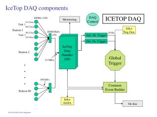
Mott DAQ crates VME Crate Mott NIM Crate 1 Mott NIM Crate 2
VME CRATE Gate 1 In 1 1 17 BFM 18 Mott DetTr L1A LEMO 4 Common LN1 L1A ECL 4 TRG IN TRG IN Opsmdaq0 nT_Settle
Mott Detector Trigger Logic Diagram Shaping Delay = 4 ns Thresholds: LEFT: -25 mV RIGHT: -25 mV UP: -30 mV DOWN: -30 mV FADC S1 E Detector FANOUT Timing DISC S1 Shaping Delay = 2 ns Thresholds: LEFT:-25 mV RIGHT: -29 mV UP: -27 mV DOWN: -42 mV S1 L S1 R U Mott DetTr D Timing DISC ΔE Detector Veto Octal DISC Delay Box FANOUT Thresholds: LEFT: -185 mV RIGHT: -189 mV UP: -185 mV DOWN: -186 mV FADC
HELICITY SIGNALS T_Settle Pair -Sync Pattern-Sync Delayed Helicity
CHANNEL ASSIGNMENT – MOTT FADC Signals on Scope Mott Trigger Left E Left ∆E Signals in FADC Data
CONTROL CHANNEL ASSIGNMENT – GATED SCALER S1 • nT_Settle Trigger Setup: • nT_Settle Trigger is delayed by 0.4 µs • LNE is delayed by 0.2 µs nT_Settle nT_Settle LNE Delayed TID nT_Settle Trigger (Scalers )
Beat Frequency Modulation (BFM) – Hansknecht (new) BFM after -450 mV offset BFM BFM, after 0.01 µF Coupler BFM after -200 mV discrimination (TDC) BFM in FADC, Range=1.0 V
Beat Frequency Modulation (BFM) – Musson (old) BFM after -140 mV offset BFM, after 0.01 µF Coupler BFM after -145 mV discrimination (TDC) BFM in FADC, Range=0.5 V