Corrosion Training
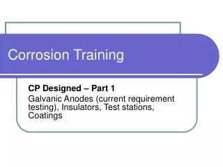
Corrosion Training. CP Designed – Part 1 Galvanic Anodes (current requirement testing), Insulators, Test stations, Coatings. Learning Over View. Part One – Current requirement design Galvanic anode design Insulators Coatings Test stations Coupons Part Two –

Corrosion Training
E N D
Presentation Transcript
Corrosion Training CP Designed – Part 1 Galvanic Anodes (current requirement testing), Insulators, Test stations, Coatings
Learning Over View • Part One – • Current requirement design • Galvanic anode design • Insulators • Coatings • Test stations • Coupons • Part Two – • Rectified Systems, Solar panels • Part Three – • AC Design
Objective of Class • Understanding of design for COH and CKY with Corrosion • Anodes (Galvanic) • Insulators (types) • Coatings (types) • Test stations • IR Coupons
Galvanic Anodes – Types? • Magnesium anodes are used for galvanic anodes in our system • 17lb anode - remediation of WT pipelines • 17lb anode - new steel coated pipe • 9lb anode - bare main or service • 3lb anode - bare customer service • 1.5lb drive in anode – company or customer metallic coated risers • 1.0lb zinc serv-a-node
Galvanic Anodes – When? • Any time a metallic pipeline is exposed and the surface of the pipeline is disturbed and the pipe to soil readings are below -1.000 V CSE. • Any time corrosion technician has indicated on corrosion recommendations • CP mains reading below -.850 V CSE on a 2512 J.O. (annual monitoring) • Cost and application evaluation performed for comparison of anodes vs. solar vs. rectified systems
Galvanic Anodes – Connected? • Thermite welded to the pipeline • Thermite welds shall be 4” apart from each other • Thermite welds shall be 6” away from an adjacent weld • At any test station locations, connected by mechanical means by junction of the test station terminal
Galvanic Anodes – Design? • Current Requirement test • Soil resistivity test • Determine the output of a 17lb HP anode • Number of anodes = Icp/Ia • Sunde theory
Galvanic Anode – Design (new Coated Steel Main) • Surface Area of pipeline • Diameter • Length • Coating Effectiveness • Current Density • Soil Resistivity
New Steel Pipe Calculations – Number of anodes • For an example – • First calculate the total surface area of 6” WT MP pipe at a length of 12,000 feet? • Use the formula • Total surface area = Diameter x Length x
New Steel Pipe Calculations – Number of anodes • For an example – • First calculate the total surface area of 6” WT MP pipe at a length of 12,000 feet? Keep in mind, a 6 inch diameter pipe is truly 6.625 inches R Length Area 3.14 • (6.625) = 1.735 • 12,000 = 20,820 sq ft 12 Need to divide the diameter by 12” to convert to feet
New Steel Pipe Calculations – Number of anodes • Next Calculate the total coating effectiveness • The coating effectiveness will decide the total bare area that the CP current will be needed • Keep in mind, the CP current protects only the holiday areas of the pipeline • Calculate Coating Effectiveness % • 99.5 % - Great • 98.5% to 99.5% - Good • 95% - Fair • Less than 95% - Poor
New Steel Pipe Calculations – Number of anodes • Next Calculate the total coating effectiveness • The coating effectiveness will decide the total bare area that the CP current will be needed • Keep in mind, the CP current protects only the holiday areas of the pipeline • Calculate Coating Effectiveness % • 99.5 % - Great (Columbia’s Standard used) • 98.5% to 99.5% - Good • 95% - Fair • Less than 95% - Poor
New Steel Pipe Calculations – Number of anodes • What is the total surface area?
New Steel Pipe Calculations – Number of anodes • What is the total surface area? • 20,820 sq ft • What is the total bare area of the pipeline?
New Steel Pipe Calculations – Number of anodes • What is the total surface area? • 20,820 sq ft • What is the total bare area of the pipeline? • 104.1 sq ft
New Steel Pipe Calculations – Number of anodes • Next calculate the total amount of current requirement for CP of the pipeline • Total bare area x current density = ICP • What is the bare area? • 104.1 sqft • What is the current density?
New Steel Pipe Calculations – Number of anodes • Current Density • Is considered the square of the pipeline in which will conduct current • Normally in the range 1 to 3 mA • Sandy or Dry soil – 3 mA • Semi-dry soil – 2 mA • Wet soil – 1 mA • For current requirement calculations, we use a higher number for higher soil resistivity for the purpose of designing a higher amount of current requirement.
New Steel Pipe Calculations – Number of anodes What if the soil was very sandy and normally dry? • Next calculate the total amount of current requirement for CP of the pipeline • Total bare area x current density = ICP • 104.1 x 1mA = 104.1 mA’s Bare Area of pipeline Current density Total amount of current requirement
New Steel Pipe Calculations – Number of anodes • Next calculate the total amount of current requirement for CP of the pipeline • Total bare area x current density = ICP • 104.1 x 3mA = 312.3 mA’s Bare Area of pipeline Current density Total amount of current requirement Change current density to a higher number, such as 3 mA’s
New Steel Pipe Calculations – Number of anodes • Number of anodes = Icp/Ia • What is the total requirement for wet soil? • Based on our calculations = 104.1 mA’s • How many anodes needed? • Have to calculate anode output next??? 120,000 • f • y ρ
New Steel Pipe Calculations – Number of anodes The top three numbers are given based anode design, such as shape and weight of anode. 120,000 • 1 • 1.21 = 22.3 mA 6,500 ohms cm Anode output is calculated Input the soil resistivity to the bottom of the equation
New Steel Pipe Calculations – Number of anodes • Now with the anode output and the total amount of current requirement is calculated, • What is the total amount of anodes needed, if we decide to bank the anodes 10 feet apart? • Number of anodes = Icp/Ia • 104.1 mA / 22.3 mA = 4.6 (round to highest number = 5 anodes) • 5 anodes • Correct or not?????????? Need more anodes – Not the correct design
Sunde Theory Used for banking anodes 10 FT spacing 5 anodes 5 anodes at 10ft apart = 4.19 anodes
Sunde Theory Calculation • 5 anodes to be banked at 15 feet spacing. • 4.43 • 22.3mA = 98.8 mA • The current requirement was at 104mA therefore 5 anodes would not be enough. • 6 anodes to be banked at 15 feet spacing. • 5.22 • 22.3mA = 116.4mA • The current requirement was at 104mA therefore 6 anodes would have enough output to meet cathodic protection.
New Steel Pipe Calculations – Number of anodes • Summary • 6” WT Pipe @ 12,000 length = • 5 anodes, if distributed along the line • 6 anodes, if banked at 10 feet apart • Soil resistivity of 6500 ohms cm • Current density of 1 mA • Coating effectiveness of 99.5%
Test Stations • Above Ground • Cott • Large Fink • Small Fink • Gerome • Tri-view flex • B-T • Curb box type • COH and CKY – Recommended use is the Tri-view flex for above ground use • Gerome box for any continuity or interference bonds
Test Stations • Two wires – No. 12 Black • New • Carrier pipe • Two wires – No. 12 White • Old/bare • Casing
Test Stations • Interference test station (bond) • Two No. 8 wires (1-Company & 1-Foreign) • Two No. 12 wires black (company) • Two No. 12 wires white (foreign)
Test Station - Spacing's • Business – 750 Feet • Residential – 1500 Feet • Rural – 6000 Feet • P/P - 653-3
Coatings • Coatings are our first line of defense against corrosion. • Coatings are a high resistance barrier between the metallic structure and the surrounding electrolyte. • A quality dielectric coating material can reduce costs in additional corrosion control materials such as sacrificial anodes or impressed current type cathodic protection systems.
Coatings • Cathodic protection system design is based upon protecting the bare surface area of the buried/submerged metallic structure. • Typically a well coated pipeline will be protected over 90% of its surface. • In this case, only 10% of the pipeline surface will require cathodic protection current.
Coatings • As an example: • 100 feet of 12” diameter pipe has 314 ft2 of surface area. • A vertically installed 17# high potential magnesium anode in 5000 Ω-cm soil has a current output of 30 mA. • A design current density of 2 mA/ft2 results in a current requirement for the pipe of 628 mA. • With 30 mA per anode, 21 anodes are required. • However, if the pipe is 90% coated, then only 10% or 31.4 ft2 is bare. • At 2 mA/ft2 the current requirement is 62.8 mA. • With 30 mA per anode, only 3 anodes are required! • This shows the importance of having a quality coating.
Coatings • Holiday Testing (Jeeping) • Test process which the operator can identify holidays (imperfections) in the coating • Involves a high voltage power source • Instruments can be adjusted to apply the proper voltage across the coating • Different thickness’ of coating requires different settings • Electrode is passed over the coating surface • If the coating resistance is low or a holiday is present, an audio signal is heard due to an electrical discharge from the electrode onto the pipe surface • Repair of the coating is made
Coatings – Jeep Settings Fusion Bonded Epoxy Powercrete Extruded
Coatings – Jeep Settings Some common Jeep voltage settings for common coatings
Coatings – Jeep settings • You maybe asked to QA or verify the coating thickness base on the jeep process • Check the coating thickness • DFT • Check the voltage setting of the Jeep • Verify, the contractor or crew is creating a holiday to verify the setting
Coatings • Three common types mostly used in the gas industry • Extruded • Fusion bonded epoxy (FBE) • Powercrete
Coatings • Extruded • High density polyethylene • Can be supplied in different thickness’ up to 60 mils • Asphalt or rubber butyl adhesive • Normal thickness is in the range of 10 to 15 mils • Used primarily for direct bury application • Girth welds normally coated with cold-applied tapes
Coatings - Extruded • Direct Bury - • X-Tech II – COH & CKY practice for direct bury design, 1st choice • 70 mill application • Two layers of 30 mills of polyethylene coating • 10 mills of butyl rubber mastic
Coatings - Extruded • Design for AC and/or DC interference currents • Use only Extruded – X-TECH II coating systems
Coatings - FBE • Fusion Bonded Epoxy • Surface preparation includes sand blasting • To clean the surface and form anchor patterns for the coating to adhere or bond to the pipe surface • Surface is acid washed to remove salt deposits • Surface is washed with dionized water • Pipe surface is heated to 500 degrees or hotter • Epoxy powders are electro statically charged and sprayed onto the hot surface • The powders melt to a liquid form and fuse to the pipe surface forming a hard shell • The applied coating normally cures within 90 seconds and then is blasted with cool water in order to facilitate handling
Coatings - FBE • FBE • 12 – 15 mills of FBE first layer • 20 mills of FBE second layer • Total of 32 to 35 mills coating • COH & CKY practice – only use dual coats, never single layer systems, 2nd choice for direct bury
Coatings – Powercrete • Epoxy base Polymer Concrete • The pipe is coated with an FBE normally with a thickness of 12 to 15 mils • The FBE is then coated with the polymer concrete coating (Powercrete) 20 mills
Coatings - Powercrete • Can be applied in the field • Each pass applies approx. 20 mils thickness • Max – 125 mils • Perfect for directional boring • COH and CKY – recommendation for directional boring design • Use for above ground design with a polyurethane outer coat
Coatings - Powercrete • COH & CKY practice – a minimum of 50 mils for above ground application • COH & CKY practice – a minimum of 50 mils for directional boring application • COH & CKY practice – a minimum of 70 mils for rocky directional boring applications
Coatings – Girth Welds • Girth Welds • FBE and Powercrete coating applications • COH & CKY practice – two part liquid epoxy system • Protal 7200 – temp’s at or above 50 degrees • Protal 7125 – temp’s below 50 degrees • R95 – temp’s at or above 50 degrees – back up coating • Surface will need to be sand blasted to a Nace 1 anchor pattern • The two parts are mixed • Epoxy resin • Epoxy hardener • Coat the surface of the girth weld according to manufacture’s recommended wet film thickness • Use the same material on the holiday areas as well
Coatings – Girth Welds • Girth Welds • Extruded Coatings – X-Tech II • Acceptable methods – • Polyken 936 • Tape coat H35 • Petrolatum Tape • Utility tape (PVC) on new steel applications to be used • S105 paste recommended, especially in cold climates