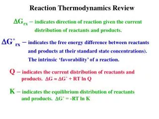
Thermodynamics Review
Thermodynamics Review. Craig Bradshaw, Lambert Fellow and PhD Candidate Slides provided by Prof. S. F. Son, and M. Mathison Adapted from Prof. G. A. Risha and other sources such as Kaplan AEC Education. THE FIRST LAW OF THERMODYNAMICS


Thermodynamics Review
E N D
Presentation Transcript
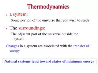
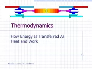
Thermodynamics Review Craig Bradshaw, Lambert Fellow and PhD Candidate Slides provided by Prof. S. F. Son, and M. Mathison Adapted from Prof. G. A. Risha and other sources such as Kaplan AEC Education THE FIRST LAW OF THERMODYNAMICS • Energy cannot be created or destroyed, but transformed into different forms • Applies to systems classified as either closed or open Thermodynamics is the transformation of energy
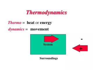
Thermodynamic Systems Energy Balance: Finite Time Energy Balance: Rate Energy Transfer by Work and Heat: Qout< 0 Win < 0 Engines burn fuel to put heat into the system and produce work (out of the system) Qin > 0 Wout > 0 What is your system? Closed (fixed mass) or open (fixed volume)
Fixed Mass: Closed System Note: Closed systems are a subset of open systems
Systems and Sign Convention Consider a system that contains a lightbulb powered by electricity. Which of the following is true? • Positive work, positive heat transfer • Positive work, negative heat transfer • Negative work, positive heat transfer • Negative work, negative heat transfer Which of the following would be considered a closed system? • A pump • A tire • A turbine • A jet nozzle + -
Closed System: Work P Boundary Work: Note that if volume is constant,W = 0 Constant Pressure: Polytropic:
Work: Special Cases (Ideal Gas) Ideal Gas Law: Constant Temperature: Isentropic: s2 = s1 specific heat ratio,
Closed System Work When using the previous equations for boundary work, it must be assumed that a quasi-equilibrium process exists. If a quasi-equilibruim process exists, we have assumed The pressure at any instant to be everywhere constant. An isothermal process. The heat transfer to be small. The boundary motion to be infinitesimally small. That no friction exists.
Control Volume: Open System Energy exiting the control volume in the forms of kinetic energy, potential energy, and enthalpy (h = u + pv) Energy entering the control volume in the forms of kinetic energy, potential energy, and enthalpy At steady-state,
Nozzles and Diffusers Assumptions: (1) adiabatic, Q = 0 (2) no volume changes, W = 0 (3) steady-state, d/dt = 0 (4) change in potential energy negligible or
Nozzles and Diffusers h-s Diagram for Nozzle Nozzle Efficiency: Compares the performance of a real nozzle or diffuser to the performance of an ideal, isentropic nozzle or diffuser operating between the same pressures Actual process Isentropic process with same initial state and final pressure
Turbines, Pumps, and Compressors Assumptions: (1) adiabatic, Q = 0 (2) change in potential energy negligible (3) steady-state, d/dt = 0 (4) change in kinetic energy negligible
Turbines, Pumps, and Compressors • Turbine and compressor/pump efficiencies both compare the performance of an actual device to the performance of an ideal, isentropic device operating between the same pressures • Turbine Efficiency:In turbines, the actual power generation will be less than the ideal power generation • Pump/Compressor Efficiency:In pumps/compressors, the actual power consumption will be greater than the ideal power consumption isentropic isentropic
Throttling Valves Assumptions: (1) adiabatic, Q = 0 (2) no volume changes, W = 0 (3) steady-state, d/dt = 0 (4) change in potential energy negligible (5) change in kinetic energy negligible
Boilers, Condensers, and Evaporators Assumptions: (1) constant volume, W = 0 (2) change in potential energy negligible (3) steady-state, d/dt = 0 (4) change in kinetic energy negligible
Heat Exchangers Assumptions: (1) constant volume, W = 0 (2) change in potential energy negligible (3) steady-state, d/dt = 0 (4) change in kinetic energy negligible (5) adiabatic, Q = 0
Example Problem 1 Given:Gas initially at 1 MPa and 150 oC receives 7.2 MJ of work while 1.5 kW of heat are removed from the system. Calculate the internal energy change for the system over a period of one hour. Analysis: negligible Work done ON system: W = -7.2 MJ Heat OUT of the system:
Example Problem 2 Given:Calculate the power required to compress 10 kg/s of air from 1 atm and 37 oC to 2 atm and 707 oC. For low pressure air: T = 310 K; h = 290.4 kJ/kg T = 980 K; h = 1023 kJ/kg Analysis: Done ON system
Example Problem 3 P B A C V Given:A gas goes through the following thermodynamic cycle. A to B: constant-temperature compression B to C: constant-volume cooling C to A: constant-pressure expansion The pressure and volume at state C are 1.4 bar and 0.028 m3, respectively. The net work from C to A is 10.5 kJ. What is the net work from one complete cycle A-B-C? Analysis:
Example Problem 3 P B A C V Constant Temperature: Need volume @ A, constant pressure A to C Compression, W<0
Example Problem 3 P B A C V Constant Temperature: Ideal gas and constant mass
PROPERTIES OF PURE SUBSTANCES • Use of Steam Tables • Use of R-134a Tables, NH3 Tables, and P-h Diagrams
Pure Substances • What is a pure substance? • Materials with unchanging chemical composition • Three common phases of pure substances: • Liquid, vapor, and solid • Also consider liquid-vapor mixtures, which are a combination of liquid and vapor where pressure and temperature are not independent • State Postulate:Two independent, intensive properties are required to fix a state • Intensive: Independent of system size (usually per mass) • Extensive: Dependent on size of system
T-v Phase Diagram Diagram courtesy of Jerry M. Seitzman, 2001.
T-v Phase Diagram @ Constant Pressure T > Tsat “superheated vapor” T = Tsat “two-phase liquid-vapor” T < Tsat “compressed liquid”
P-v Phase Diagram @ Constant Temperature P < Psat “superheated vapor” P = Psat “two-phase liquid-vapor” P > Psat “compressed liquid”
Common Properties A set of properties that completely describes a system, specifies the state of the system. • Mass, m • Extensive • Units [kg] • Volume, V • Extensive • Units [m3] • Pressure, P • Intensive • Absolute units [Pa, psia] • Gage, Pgage = Pabs - Patm • Temperature, T • Absolute units [K or oR] • T[K] = T[oC] + 273.15 • T[oR] = T[oF] + 459.67 • Specific Volume, v • Intensive • Units [m3/kg] • v = 1/r = V/m • Internal energy, u • Intensive • Units [kJ/kg] • U = m*u [kJ] • Enthalpy, h • Intensive • Units [kJ/kg] • h = u + Pv; H = U + P V • H = m*h
Properties [cont’d] • Entropy, s • S, extensive [kJ/K] • s, intensive [kJ/kg-K] • Enthalpy • H, extensive [kJ] • H, intensive [kJ/kg] • H = U + PV • h = u + Pv] • Gibbs’ Function • G, extensive [kJ] • g, intensive [kJ/kg] • g = h - Ts = u + Pv - Ts • G = H - TS = U + PV – TS
Saturated Liquid Vapor Mixture (SLVM) Quality: Quality is a function of the horizontal distances on P-v and T-v diagrams mass of vapor mass of liquid
Example • The Purdue Physics department did a demonstration of collapsing a barrel by boiling a small amount of water for several minutes, then sealing the barrel and letting it cool (see images below). Room temperature is 25oC. What is the maximum pressure difference (between the outside and inside of the barrel) possible that could be realized if the barrel were strong enough NOT to collapse?
Assume saturated vapor at atmospheric conditions. Table A-4, for p=101.42 kPa, T=100oC, yields v1 = vg =1.6720 m3/kg • At state 2: v2 = v1 =1.6720 m3/kg • The MAXIMUM pressure difference possible would be for the water vapor to be cooled to room temperature. At room temperature (25oC), vg = 45.3 m3/kg and vf = 0.001003 m3/kg. • Therefore, the water is a SLVM at 1.6720 m3/kg and 25oC. The SLVM is at the saturation pressure at 25oC, which is 3.1698 kPa. • For this process, ΔP = 101.42 – 3.1698 kPa. • Thus, the maximum pressure difference is 98.25 kPa.
IDEAL GASES • Equations of State • Enthalpy and Internal Energy Changes
Ideal Gas Equation of State P pressure [Pa] V volume [m3] m mass [kg] R gas constant [J/kg-K] T temperature [K] r density [kg/m3] v specific volume [m3/kg] n number of moles [mol] Ru universal gas constant [J/kmol-K] MWgas molecular weight [kg/kmol] Ru = 8.314 kJ/kmol-K = 8314 J/kmol-K = 1.986 cal/mol-K
Ideal Gas Relationships Specific Heats: constant volume specific heat [kJ/kg-K] cp – cv = R gas constant [kJ/kg-K] constant pressure specific heat [kJ/kg-K] Internal Energy: Enthalpy: (Assuming constant specific heat) Du = cvDT [kJ/kg] Dh = cpDT [kJ/kg] Entropy: (Assuming constant specific heat)
Ideal Gas Relationships Constant Temperature: Constant Pressure: Constant Volume:
Isentropic Ideal Gas Relationships Isentropic with constant specific heats: k = specific heat ratio
Non-ideal Gases • Gases behave ideally at low pressures and high temperatures • What is meant by low pressure and high temperature? • Compressibility factor quantifies the deviation of a pure substance from ideal gas behavior at a given temperature and pressure • Z = 1 (ideal gas) • For a real gas, Z > 1 or Z < 1 • For Z very close to unity, we can assume ideal gas behavior, most of the time
Compressibility Factor • Reduced pressure and temperature: • PR = reduced pressure; TR = reduced temperature • Pcr = critical pressure; Tcr = critical temperature • Principle of Corresponding States: The compressibility factor is approximately the same at the same PR and TR for all fluids • Therefore, a generalized compressibility chart can be used to find the compressibility factor of any fluid
Generalized Compressibility Chart Sonntag, Borgnakke, and Van Wylen, Fundamentals of Thermodynamics, 5th Edition, page 763.
Property Evaluation • STEP 1: ALWAYS start in the saturated or “two-phase liquid-vapor” tables • STEP 2: Identify two, independent, intensive properties • Pick one property and find its location; compare the second using the following rules: • If the properties are pressure and temperature, and • Tsat < T or Psat > P, then “superheated vapor” • Tsat > T or Psat < P, then “compressed liquid” or “sub-cooled” • Tsat = T or Psat = P, then “liquid-vapor” and need another property • If one of the properties is not pressure or temperature • Let b be your property • b > bg, then “superheated vapor” • b < bf , then “compressed liquid” or “sub-cooled” • bf< b < bg, then “liquid-vapor”
Property Evaluation STEP 3: Evaluate the remaining properties If “superheated vapor,” then go to superheated tables If “compressed liquid” or “sub-cooled,” then go to compressed liquid tables If data does not exist, assume the following: v = vf h = hf u = uf s = sf where the saturated liquid property is evaluated at the given temperature since pressure does not impact liquids that much If “liquid-vapor,” then continue using the “two-phase liquid-vapor” tables and find quality
Example 1 Given:Steam at 2.0 kPa is saturated at 17.5 oC. In what state will the steam be at 40 oC if the pressure is 2.0 kPa? Analysis: @ P = 2.0 kPa = 0.02 bar, and T = 40oC Psat > P “superheated vapor”
Example 2 Given:What is the change in internal energy of air (assumed to be an ideal gas) cooled from 550 oC to 100 oC (assume constant cv= 0.718 kJ/kg-K) ? Analysis: “ideal gas” Du = cvDT = cv (T2-T1) given cv= 0.718 kJ/kg-K Du = 0.718 kJ/kg-K (550-100)K Du = 323.1 kJ/kg
Example 3 Given:A boy on the beach holds a spherical balloon filled with air. At 10:00 a.m., the temperature on the beach is 20 oC and the balloon has a diameter of 30 cm. Two hours later, the balloon diameter is 30.5 cm. Assuming the air is an ideal gas and that no air was lost or added, what is the temperature on the beach at noon? Analysis: “ideal gas” constant mass, constant pressure, and same gas,
Example 4 Given:Steam initially at 1 MPa and 200 oC expands in a turbine to 40 oC and 83% quality. What is the change in entropy? Analysis: @ P1=1 MPa = 10 bar, and T1=200 oC >> Psat > P “superheated vapor” @ T=40 oC and x2 = 0.83 “two-phase liquid-vapor”
Example 4 - Cont’d Given:Steam initially at 1 MPa and 200 oC expands in a turbine to 40 oC and 83% quality. What is the change in entropy? Analysis: s1 = 6.6940 kJ/kg-K (from superheated table for 1 MPa, 200 oC) @ 40 oC, s2,f = 0.5725 kJ/kg-K; s2,g = 8.257 kJ/kg-K s2 = s2,f +x2(s2,g-s2,f) = 0.5725+0.83*(8.257- 0.5725) s2 = 6.9506 kJ/kg-K s2 - s1 = (6.9506 – 6.694) kJ/kg-K s2 - s1 = 0.2566 kJ/kg-K
Example 5 Given:A 3 kg mixture of water and water vapor at 70 oC is held at constant pressure while heat is added. The enthalpy of the water increases by 50 kJ/kg. What is the change in entropy? Analysis: Ds = 0.1458 kJ/kg-K Heat flow = enthalpy change since integrate