Download
1 / 27
330 likes | 794 Vues
Solder Joint Reliability Assessed by Acoustic Imaging during Accelerated Thermal Cycling. Ryan Yang 05/03/2010 G M Zhang, D M Harvey Electronic and Ultrasonic Engineering Group GERI. Presentation Outline. Introduction Accelerated Thermal Cycling Acoustic Micro Imaging

E N D
Solder Joint Reliability Assessed by Acoustic Imaging during Accelerated Thermal Cycling Ryan Yang 05/03/2010 G M Zhang, D M Harvey Electronic and Ultrasonic Engineering Group GERI
Presentation Outline • Introduction • Accelerated Thermal Cycling • Acoustic Micro Imaging • Feature Extraction & Blob analysis • Test and Analysis • Future Work & Conclusion
Introduction • Solder joint reliability is a primary concern in the assembly of all Electronic components and products. • The importance of solder joint reliability became more emphasized in recent years as a result of three factors: • 1) The shift from leaded to lead-free solders in semiconductor industry. • 2) Shrinking in die size as well as solder balls dimension. • 3) The emergence of fine-pitched area array packages that employ hundreds of solder joints for electrical connection.
Introduction • “How long will this component last?” • Solder joints reliability is the ability of solder joints to remain in conformance to their mechanical and electrical specifications over a given period of time, under a specified set of operational conditions. • It is a measure of the likelihood that a solder joint will not fail throughout its intended operating life, subject to various thermo-mechanical stresses that it encounters in its operation. • It is extremely important especially in automotive, avionics and defence industries since the electronics operate in harsh environments.
Introduction • Solder joints failures can be attributed to three core factors: • Fracture – Tensile rupture/fracture through mechanical overloading • Drop, Force fitting, Collision, • Creep – Long Lasting permanent loading • Board Warping, Weight, Pressure • Cyclic Fatigue – Cyclic loading • Thermal Cycling, Power Cycling, Vibration
Accelerated Thermal Cycling • Most fatigue failures are attributed to the thermo-mechanical stresses in the solder joints caused by Coefficient of Thermal Expansion (CTE) mismatch. Plastic Deformation Imposes Cyclic Strain Crack Initiation and Growth Figure 1: CTE mismatch producing cycling stress
Accelerated Thermal Cycling • The reliability assessment of solder joints under creep-fatigue effect can be carried out by Accelerated Thermal cycling (ATC) tests. Temperature Tmax +125C Hot Dwell Cold Dwell Tmin Ramp Rates -40C Figure 2: Illustration of the Thermal Cycle Time
Accelerated Thermal Cycling • ATC test result will be used to: • Estimate field product reliability • Provide data for Numerical (FEA) model • Verify and validate the FEA model • Conventional Inspection Techniques: • Electrical Resistance Measurement • Physical Micro-sectioning • Destructive • Not allowed for detailed study • Destroy Evidence
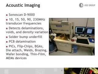
Acoustic Micro Imaging • Acoustic Micro Imaging (AMI) • Non-destructive inspection • Makes use of the properties of ultrasonic waves which range from 5MHz to 500MHz • Reflected, refracted or absorbed with respect to the differences between acoustic impedances Figure 3: Reaction of ultrasound wave in an object
Acoustic Micro Imaging Face down Chip Metalized Pads Underfilled Solder balls Connectors Test Board Figure 4: C-scan image of the Flip chip substrate-bump interface
Feature Extraction Solder joint Detection Feature Extraction Analysis / Inspection • Gradient-based Hough Transform • Blob Analysis • Tagging and Labelling • Number of Joints • Histogram • Intensity ratio • Rule-based analysis • Template-based analysis • Mask Solder joint region • Extract Masked Solder joint features • Intensity • Gradient • Area • Centroid
Feature Extraction Gradient-Based Hough Transform Figure 5: 2D and 3D view of Accumulation Array from Circular Hough Transform
Feature Extraction Gradient-Based Hough Transform Figure 6: Raw image with circle detected
Feature Extraction Tagging and Labelling Figure 7: Image of all solder joints with tag and label
Feature Extraction Mask solder joints region Figure 8: Image of all solder joints cover with mask
Test and Analysis Test Board Figure 7: Photograph of completed circuit board (front and back)
Test and Analysis Thermal Profile Figure 8: Thermal Profile of the circuit board under test
Test and Analysis R0M2 Figure 9a: Flip Chip U23 before thermal cycling Figure 9b: Flip Chip U23 after 500 cycles thermal cycling
Test and Analysis Figure 10: Histogram of Flip Chip U23 solder joint R0M 2
Test and Analysis Figure 10: Comparison of good and bad joints by ratio of bright pixels
Test and Analysis Figure 11: Microscope image of flip chip and PCB with solder joints left on the PCB board after thermal cycling
Test and Analysis Figure 12: Magnified Microscope image of flip chip and PCB with solder joints left on the PCB board after thermal cycling
Results and Analysis Figure 9a: Test Board 04_04, Flip Chip U26, Solder Joint BBM 19
Results and Analysis Figure 10: Comparison of BOTTOM-BOTTOM joints by ratio of bright pixels
Future Work • More data analysis will be carried out, such as: • Template-based analysis • Rule-based analysis • Automated feature extraction • Defect classification • Large amount of sample image and data will be tested using above analysis system. • The system will be used in recording the variation of image parameters during the thermal cycling test. • Physical cross section analysis and SEM analysis will be used to verify the results.
Conclusion • An Accelerated thermal cycling test has been carried out. • A feature extraction and blob analysis system has been discussed and results of the inspection are shown. • Accelerated thermal cycling test is one of the key tools for evaluating solder joints reliability. • Inspecting the samples is time consuming and mostly dependant on the operator’s experiences. • A robust feature extraction and data analysis system is vital to provide more consistent and accurate analysis as well as achieve high quality inspection.