Download
1 / 21
260 likes | 747 Vues
In-Cylinder Pressure and Flame Measurement. Dr. Manoochehr Rashidi Engine Research Center Shiraz University. http://succ.shirazu.ac.ir/~motor/ motor@shirazu.ac.ir. Prepared for the 3 rd conference on IC engines, Tehran 2004.

E N D
In-Cylinder Pressure and Flame Measurement Dr. Manoochehr Rashidi Engine Research Center Shiraz University http://succ.shirazu.ac.ir/~motor/ motor@shirazu.ac.ir Prepared for the 3rd conference on IC engines, Tehran 2004
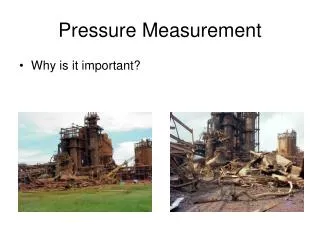
Modern engine design, development and operation, involvesmany aspects of science, technology, and engineering. Engine testing is an important aspect of internal combustion engines, as it leads to a better understanding of engine operation and performance. The use of computer control and data acquisition systems has been complemented by increasing levels of engine instrumentation. This leads to large quantities of data, and a need for effective post processing and systematic analysis of data. Increasing use of powerful computers, leads to greater optimization prior to the start of development testing. These factors are balanced by increasing restrictions on engine emissions, and difficulty of reducing engine specific fuel consumption. Another useful in-cylinder measurement is the flame propagation, flame velocity and burn rate, which is achieved with use of high speed photography. This type of results will be useful as an input to simulating engine performance and cycle analysis.
This presentation is a review of equipment and procedures, necessary for in-cylinder pressure measurement and analysis, using data acquisition equipment. Procedure and equipment for measuring pressure and flame velocity, simultaneously, are also described. Typical results showing variation of pressure, burn rare, heat release rate, and burning velocity, with crank angle; also flame photographs, are included.
Mechanical, low speed method forin-cylinder pressure measurement
High speed analog digital converter data acquisition PCI board Available for Compact PCI/PXI 4 single-ended simultaneous sample/hold A/D channels 14-bit resolution, 500 kS/s sampling rate Gains: 1, 2, 5, 10 Two 12-bit analog outputs; 32 digital I/O lines; three 16-bit counter/timers Stream-to-disk capability Calibration certificate Software for Windows Simultaneous operation of all sub systems
Pressure recorded every ½ degree, for direct injection diesel engine, 1000 rpm 60% load. (d) is the derivative of (a). (b) is derivative with smoothing applied twice. (c) is derivative after smoothing trace (a) twice.
Equation for calculatingfuel heat release ratefrom pressure data
Variation of cylinder pressure and inlet pressure at enginepart load for one cycle. The valve timing is also shown
Effect of combustion chamber design on rate of pressure rise, combustion duration, and octane requirement.
Pressure in the intake and exhaust manifold of four cylinder Si engine. p1 is located in intake 150 mm from cylinder. p2 is located in exhaust 200 mm from cylinder. p3 is located in exhaust 700 mm from cylinder. IO and EO are inlet and exhaust open.
Pressure diagram showing normal combustion (a),slight knock (b), and intense knock (c).
Simultaneous measured pressure at two locationsin engine with combustion knock.
Pressure and Rate of Heat release Diagram Showing Cycle by cycle Variation