Structures and Weights 1 QDR
Structures and Weights 1 QDR. AAE 451: Team 2. Michael Caldwell Jeff Haddin Asif Hossain James Kobyra John McKinnis. Kathleen Mondino Andrew Rodenbeck Jason Tang Joe Taylor Tyler Wilhelm. Overview. Wing Structure Geometric Layout Properties of Wing Box Material Properties

Structures and Weights 1 QDR
E N D
Presentation Transcript
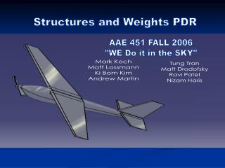
Structures and Weights 1 QDR AAE 451: Team 2 Michael Caldwell Jeff Haddin Asif Hossain James Kobyra John McKinnis Kathleen Mondino Andrew Rodenbeck Jason Tang Joe Taylor Tyler Wilhelm
Overview • Wing Structure • Geometric Layout • Properties of Wing Box • Material Properties • Structural Geometry • Wing Loading Analysis • Landing Techniques • Weight Estimate
Aircraft 3-View Mission Requirements • 15 min. endurance • Take-off distance ≤ 60 ft. • Vstall ≤ 15 ft./s • Vloiter ≤ 25 ft./s • 35 ft. turn radius
Properties of Wing Box • Shear Web • 1.6 in. x 0.125 in. (0.1333 ft. x 0.0104 ft.) • Wing Spar • Central I beam located at maximum wing thickness • With shear web and two stringers • Ribs • Balsa • 20 ribs spaced approximately every 3 inches • Stringers • Balsa • 0.375 in. x 0.375 in. (0.03125 ft. x 0.03125 ft.) leading edge stringer • 0.375 in. x 0.75 in. (0.03125 ft. x 0.0625 ft.) trailing edge stringer for mounting aileron • Monokote wing covering • All parts: 11 lbf/ft3 balsa • High safety factor (oversized web/stringers)
Structural Geometry • Balsa construction • Lightweight • Simple, quick construction • Monokote covering
Wing Loading Analysis • Constraints • Analysis • Load Distribution at Maximum Wing Loading • Maximum Wing Root Bending Moment • Maximum Torsional Moment
Bending • Worst case simplification • cantilevered beam • uniform load distribution • negligible outer fuselage mass/support
Twisting • Moment due to lift found from moment coefficient
Constraints • Twisting: less than one degree of twist • Bending: bending stress less than balsa yield stress (w/ safety factor of 2)
Analysis • Maximum wing load: • 1.97 lbs of lift, assuming uniform distribution and span • Maximum bending moment (at root): • 1.308 ft-lbs • Maximum torsional moment (from Cm): • 0.194 ft-lbs
Landing Techniques • Belly Landing • Conventional Landing Gear • Landing Skis • Parachute • Catching Net
Weight Estimate • Weights of parts: • Fuselages: 0.317 lbf • Wing: 0.579 lbf • Canard: 0.133 lbf • Tails: 0.146 lbf • Motor: 0.172 lbf • Batteries: 0.113 lbf • Distance measured from front of aircraft • CG = 1.482 ft • AC = 1.589 ft • Static margin = 10.7%
Summary • Wing Structure • Geometric Layout • Properties of Wing Box • Material Properties • Structural Geometry • Wing Loading Analysis • Landing Techniques • Weight Estimate • Questions?
Airfoil Selection: Wing Wortmann FX 63-137 Wortmann FX 63-137: M.S.Selig,J.F.Donovan and D.B.Fraser,"AIRFOIL AT LOW SPEEDS” – Wind Tunnel
Airfoil Selection: Canard NACA 0012