Download
1 / 53
540 likes | 552 Vues
This project aims to develop a compact and high-performance laser transceiver system for communication between UAVs. The approach includes the use of scanning mirrors and gyros, as well as COTS components. The team has made progress with the MEMS mirror process and the development of the CMOS integrated imaging receiver. The goal is to achieve a data rate of 1 Mbps over a distance of 5 km.

E N D
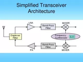
Steered Agile Laser Transceiver B. Boser, K. Pister BSAC, EECS, UC Berkeley Steve Morris, MLB Co.
2-pronged Approach • Scanning mirrors • Best performance, hard fabrication process • Modest performance, high yield • Gyros • BSAC research funded elsewhere • COTS (ADRS150) • Optical Receiver • Exotic, high performance design • Straightforward,currently working design • System design • laboratory demo: SALT cube • MAVs: Larger, more power hungry and robust
Progress/Personnel • MLB under contract for aircraft, software • Hired 3 staff engineers • Anand Jog, PhD; project manager • Software and MEMS engineers • Total students affiliated: 10 • Consulting engineer for COTS system controller
Cambridge 6200 Scanner • Smallest 2-d Scanner on the market • 1-2 kHz bandwidth • +/- 20 degree deflections • +/- 15-28 volt input requirement • Total circuit requires 10Amps per axis • Linearity is 99.5% • 8 Microradian repeatability 6200 Scanners Alone Scanners with Servo Boards
Lateral pull single-crystal silicon mirror From lateral actuators/sensors anchor anchor Back-side etched cavity
Start with DSP 2um SOI, 1um BOX MEMS Mirror Process
Bond to clean, chemically activated, unoxidized, SOI wafer. Anneal @ 1050C
Deposit doped poly. Blanket etch front/backside, stop on oxide
CMOS Integrated Imaging Receiver VLSI for large number of high-speed processors (Moore’s Law) Focal-plane integration of electronics for parallel processing
Optical Limits: Examples MAV/MAV Sensor/LEO office Common Parameters: Ptrans = 5 mW (opt.) Optical SNR > 20 dB Recv’d Power > -54 dBm = 830 nm = 10 nm Rphoto = 0.25 A/W
Imaging Receiver Progress • Working 3nd generation single pixel • Minimum detectable signal strength reduced: 500 nWp-p 50 nWp-p. 20 nWp-p. • Dynamic range, stability issues solved • 80 dB dynamic range (allows 50m to 5km) • Two digital feedback loops • 5.1 km fixed point-to-point link demonstrated
General Front-End Architecture • Requirements: • Gain and offset control to ±20% full scale for accurate thresholding • Gain control must be monotonic • Rsense ranges must overlap (PGA needs fairly wide control range) • Gain control shouldn’t affect amplifier offset Rsense … + S - Fast Peak Min Slow
Direct Impedance Architecture … 1kW - 100kW, 10x steps 10dB 0/6dB 0/6dB 0/3dB … Timing Rec. Data Decoding + S - LNA A1 A5 A6 Coarse ADC Coarse DAC Control Logic • Peak detect = max ADC code over interval known to include a “1” • 73 dB gain control with 1.5 dB (20%) precision • 10 mV offset adjust precision for all amplifiers
Die Layout Noise Simulation: 1 nArms input referred noise at 100 kW sensitivity Measured Power Consumption: 30 mA @ 2.5 V (75 mW) 10 mA for LNA (50 mS) 20 mA for PGAs Manually programmable via serial bus. Fabricated and tested.
Measured Performance 40 nWpeak optical 400 nWpeak optical > 60 dB tested dynamic range with no missing levels or monotonicity errors in gain control.
Receiver/Decoder Layout Version 3 Version 2
Data Bus Arbitration • Each pixel has an associated data register • Immediately stores received data from pixel • Shifts data into next register over if it’s free • Simple logic to control data flow. • Each pixel only needs nearest neighbor connectivity (no long bus wires, no arbitration trees) Receiver Register Receiver Register Receiver Register End of Column Buffer
Data from 250m link • 15mW average power transmitter • 1mrad FWHM divergence • 100 bps square wave
Looking East from Berkeley Marina ~1 steradian
+/- 10 degrees Cory Evans Campanile
+/- 10 degrees (300mrad) Receiver pixel ~10mrad
Receiver pixel = ~10mrad square Transmitter pixel <1mrad square
Data from 5.1 km link • 15mW, 1mrad, 1Mbps TX • 2cm RX aperture • 40nW optical power received, ~800x less than 250m link • Low link availability due to turbulence
1st Gen. Gyro-stabilized Scanner MEMS Scanner 2 single-axis STEC mirrors Laser Gyro boards