Download
1 / 7
70 likes | 174 Vues
This guide provides a detailed comparison of the wiring configurations for the Yaskawa GPD 315 and V1000 inverters. It covers input, output, braking resistor connections, and control terminal block (TB) wiring for both models. Key wiring points like main power inputs (L1, L2, L3), outputs (T1, T2, T3), and additional components such as DC reactors and contact outputs are clearly explained to ensure users understand the differences and connections needed for efficient operation.

E N D
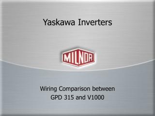
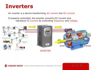
Yaskawa Inverters Wiring Comparison between GPD 315 and V1000
Old Lug Wiring • Old GPD 315 • L1, 2, and 3 Main Input • T1, 2, and 3 Main Output • B1 and 2 Braking Resistor • +1 and 2 DC Reactor
New Lug Wiring • New V1000 • L1, 2, and 3 Main Input • T1, 2, and 3 Main Output • B1 and 2 Braking Resistor • +1 and 2 DC Reactor
Old GPD 315 L1, 2, and 3 Main Input T1, 2, and 3 Main Output B1 and 2 Braking Resistor +1 and 2 DC Reactor New V1000 L1, 2, and 3 Main Input T1, 2, and 3 Main Output B1 and 2 Braking Resistor +1 and 2 DC Reactor Lug Wiring Comparison
Old TB Wiring • Old GPD 315 • S1 Forward Run • S2 Reverse Run • S3 External Fault • S4 Fault Reset • S5 Speed 1 • S6 Speed 2 • SC Common • FS Frequency Reference Power Supply • FR Frequency Reference Input • FC Frequency Reference Common • MA Contact Output (NO) • MB Contact Output (NC) • MC Contact Common
New TB Wiring • New V1000 • S1 Forward Run • S2 Reverse Run • S3 External Fault • S4 Fault Reset • S5 Speed 1 • S6 Speed 2 • SC Common • +V Frequency Reference Input Power Supply • A1 Frequency Reference Input • AC Frequency Reference Common • MA Contact Output (NO) • MB Contact Output (NC) • MC Contact Common
Old GPD 315 S1 Forward Run S2 Reverse Run S3 External Fault S4 Fault Reset S5 Speed 1 S6 Speed 2 SC Common FS Frequency Reference Power Supply FR Frequency Reference Input FC Frequency Reference Common MA Contact Output (NO) MB Contact Output (NC) MC Contact Common New V1000 S1 Forward Run S2 Reverse Run S3 External Fault S4 Fault Reset S5 Speed 1 S6 Speed 2 SC Common +V Frequency Reference Input Power Supply A1 Frequency Reference Input AC Frequency Reference Common MA Contact Output (NO) MB Contact Output (NC) MC Contact Common TB Wiring Comparison