High Voltage Test System Update: 2005 Results and March-May 2006 Developments
This report presents an update on the high voltage test system developed in J. Long, Indiana. It summarizes results from 2005 and details developments from March to May 2006, including investigations into polished electrodes and liquid helium (LHe) testing. Key findings indicate maximum electric field strengths and breakdown properties, revealing that electrode surface finish and LHe purity do not limit system performance. Remaining R&D projects focus on further breakdown diagnostics and potential improvements to prototype materials. More work is outlined for enhancing measurement precision and reliability.

High Voltage Test System Update: 2005 Results and March-May 2006 Developments
E N D
Presentation Transcript
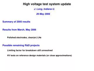
High voltage test system update J. Long, Indiana U. 26 May 2006 Summary of 2005 results Results from March, May 2006 Polished electrodes, clean(er) LHe Possible remaining R&D projects Limiting factor for breakdown still unresolved HV tests on reference design materials (or close approximations)
High voltage system prototype at LANL Test proposed amplification method LHe bath pumping line Measure breakdown properties of large volumes of LHe Existing data: 150 kV/cm at 4 K, 1cm gap Supply cryostat wire seal flange aluminum plate G-10 standoff stainless can HV feedthrough quartz window HV plunger control rod ground control rod Vacuum chamber Actuator Vacuum-LHe HV feedthrough bearings Indium seal bellows 0.53 m ceramic standoff ground electrode HV electrode
First results from prototype system arxiv: physics/0603231 Maximum potentials sustained: 11.8 liters Normal State (4.38 K), 7.2 cm gap: (96 ± 7) kV/cm 12.8 liters SF at 2.14 K, 7.8 cm gap: (31 ± 3) kV/cm Large wire-seal flanges hold SF LHe (thermal gradients > 60 K / 60 cm) Maximum leakage currents (95% C. L.) : SF (2.07 K): 733 pA Normal State (3.98 K): 169 pA Small HV feedthrough exceeded maximum rating in air (40 kV) by 25% when immersed in SF Short-duration breakdown not affected by neutron radiation (106/s, ~MeV) Standard bearings (steel, plastic-encased) and welded bellows OK for electrode position control in SF
E-field specification (M. Cooper 5/25/06) Optimal performance: saturated LHe not limiting factor if T > 3.1 K (P > 200 torr) Minimal performance: saturated LHe not the limiting factor if T > 2.0 K (P > 25 torr) After modifications of March and May 2006: cannot make a stronger statement
Recent Modifications New readout with amplifier connected to oscillating ground electrode Short t scales: i = V (dC/dt) Long t scales: iLEAK = C (dV/dt) Microamp signals (previous: nA) January-March 2006 ~ pA leakage currents detectable in a few hours Electrodes (Aluminum) polished Operation with DR pump on LHe bath (~30% more speed, cooling power) all surfaces 16 m-inch finish (previously 64 m-inch) Expect ~ 2x breakdown field improvement for ~ 5x surface roughness reduction (?) [Gerhold, IEEE Trans. on Dielec. and Elec. Insul., 1 (1994) 432-439] April-May 2006 Reliable LHe level sensing Filter on transfer line (~ 10 mm pores)
Recent HV test system operation March 2006 DAQ too cumbersome to be used for more than 3 leakage current runs - Need ~ 1 wk more programming “Hybrid” method (ground electrode as DC probe of HV) inconclusive - Analysis still in progress Trip-off and backstreaming of DR pump -> mm-sized frozen contaminants coating electrode surfaces before any data obtained New leakage current results: (5 ± 1) pA [1.8 K, 3 kV on 8 cm gap] (10 ± 2) pA [4.0 K, 70 kV on 8 cm gap] - Correct to within overall scale factor ~2 (capacitance mis-measurement) May 2006 Cleaner LHe (10 mm pore filter), no visible contaminants (except last run) Careful measurement of maximum V for 0.2 – 2.0 cm gap at 1.8 and 4.0 K
Recent small-gap results Extrapolates to 96 kV/cm at 8 cm Extrapolates to 31 kV/cm at 8 cm closed points = SF open points = normal state Blue = 2005 results Black = filtered LHe Power supply saturated Red = heavy contaminants Electrode finish, LHe purity (in range from poor to ghastly) not limiting factors in the HV test system Degradation below 1.9 K: LHe level possibly below tops of electrodes
Remaining R&D projects ~ simplest to most complex More careful purification tests (still limiting factor?) Charcoal or other filter on LHe delivery line LN2 trap on LHe bath pumping line (in absence of dry system) - Few x $1000, few weeks depending on lead times Breakdown tests on prototype holding cell (surprises…) Material (acrylic, pyrex?, d-polystyrene layer?, d-TPB coating?) Dimensions (10 x 10 x 8 cm possible, want hollow?, mounted in recesses in electrode?) More breakdown diagnostics? - Hollow coated box with no electrode modification: $10 k (incl. design, LHe), 2 mo. Replace the aluminum electrodes (more surprises…) Material (acrylic coated with graphite, diamond?, how apply coat?) - Total assuming 2 x cost and delivery of existing electrodes ~ $10 k, 3 mo.
Remaining R&D projects ~ simplest to most complex Kerr measurement ~ $30 k, 4 months, depending on optical system element lead times Assumes no provision for background subtraction scheme HV tests in pressurized SF LHe Useful to de-couple P and T effects on breakdown, even to 1.5 K If not completely intractable for actual EDM experiment (valves, heat loads), at least get engineering drawings for upgrade of HV test system D. Haase has developed design, vetted by S. Penttila (heat loads, thermal expansions, pressure measurement) ~ $30 k, 6 months HV tests at 0.5 K Install HV test system central volume in 3He R&D cryostat Need ~ 1 dedicated month for initial tests, ~2 week dedicated slots for other tests Sacrifice test system until installed (~ 3 months?) Smaller pair of fixed electrodes installed in a DR?