Programmable Timer
Programmable Timer. Mohamad KHALIL. clock ( external or internal). 16 bit counter. control circuit. Programmable Timer. The basic unit – counter (up or down) a clock source generate timing events (interrupts or timer output) if overflow or reach 0 if match with a preset value

Programmable Timer
E N D
Presentation Transcript
Programmable Timer Mohamad KHALIL
clock ( external or internal) 16 bit counter control circuit Programmable Timer • The basic unit – counter (up or down) • a clock source • generate timing events (interrupts or timer output) • if overflow or reach 0 • if match with a preset value • measure time – read counter values • free running, reset or reload, compare
interrupt 0? 16 bit counter E clock (2MHz) load counter register (499) Real-time Clock • Typical approach – • hardware unit generates an interrupt per unit of time (millisecond) • software counter (in memory) – increment when interrupted • assume E clock is 2MHz (0.5x10³ ms) • set a counter to 499 and count down with E clock • when reach 0 – • interrupt • reload the counter with 499
5 4 3 2 1 0 6 5 4 3 2 1 0 6 5 Waveform Generator • Instead of interrupt, using the pulse to generate a square wave • To generate a square wave of 96KHz, what value should be loaded into the counter?
Wave Generator (continued) • Variable duty cycle • need one more counter • application to digital-to-analog conversion • Single shot • Gated clock signal • Counter reset • reset signal • read and write operations
clock 16 bit counter load event interrupt or ready flag edge detection input capture register Measurement • Input-capture : identify the moment that an event occurs • latch the counter value when triggered • CPU can read the value later • Output compare : control the timing of output bit • CPU set a value in output compare register • comparison with counter every clock cycle • if equal, send an output signal • external event counting • measuring elapsed time, pulse width, frequency, and period
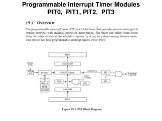
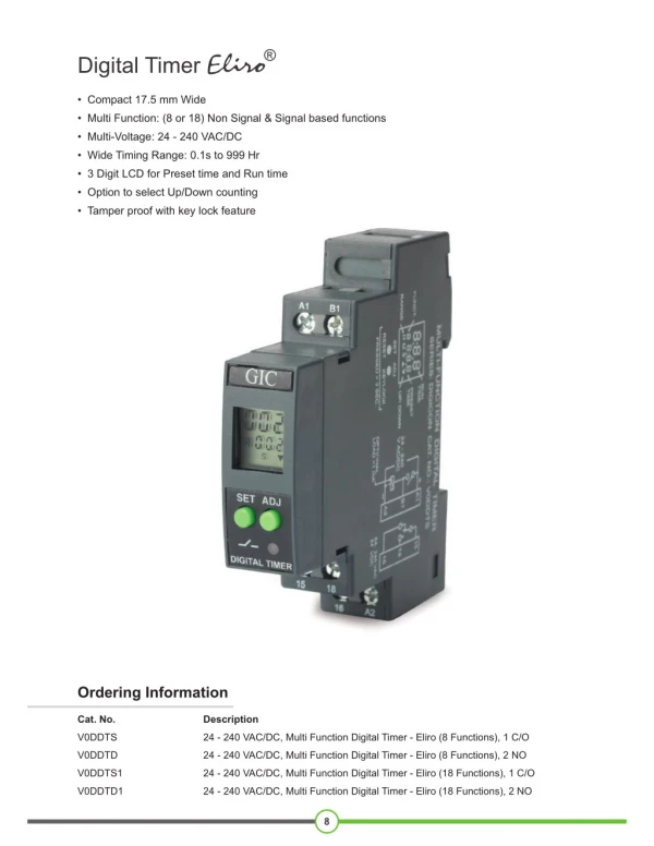
MC 6840 Programmable Timer Module • 3 16-bit counters • receive initial value from latch • halt or recycle • 3 16-bit data latches, comparison, and enable circuit • Register selection
Initialization • Reset: hardware or CR1-bit 0 • Counter latch initialization – • write to MSB and then LSB • Counter initialization – transfer data from latch to counter, clear flag and interrupt • when reset, write to latch, or negative transition of G • Operating modes
Continuous Wave Synthesis • Counter initialized, and enabled by RESET and G • Count down every clock cycle (starting from negative edge) • E clock • external clock (clocked in by E clock) • Square wave (16-bit counter) or variable duty cycle (8-bit M ad L counters)
(N+1)*E_cycle (N+1)*E_cycle 1 9600*16 Clock for ACIA • 9600 baud rate and divided by 16 in ACIA (N+1) * E_cycle *2 = 1 / (9600*16) N = 1 + E_frequency / (9600*16*2)
start counting stop counting Wave Measurement in 6840 • Pulse width comparison • Timeout period defined by counter initialization and clock period • If timeout period is longer than the pulse width, counter is disabled and interrupt flag set • read counter value to know the width
Status register • Status
Initialization • PTM initialization • To initialize the PTM, two steps are to be followed: • Store in the LATCHES the preset values. • Store in the control registers the suitable control words. • Note: the LATCHES are by default loaded by $FFFF if they are not initialized by the preset values. The data transfer from the LATCHES to the counters occurs when the counters are initialized. • The initialization of counters is done: • By activating the RESET input. • By setting to one CR10. • By initializing the LATCHES by the preset values. • By applying a negative edge transition at the Gate input.