Download
1 / 51
540 likes | 865 Vues
MT8222A BTS Master. High Performance Handheld Base Station Analyzer. AKOct05. MT8222A BTS Master Test Set Description. Product Outline: Antenna and Cable Analyzer 10 MHz to 4 GHz Spectrum Analyzer 100 KHz to 7.1 GHz T1 Tester Interference Analyzer Power Meter Measurement

E N D
MT8222A BTS Master High Performance Handheld Base Station Analyzer AKOct05
MT8222A BTS MasterTest Set Description Product Outline: • Antenna and Cable Analyzer • 10 MHz to 4 GHz • Spectrum Analyzer • 100 KHz to 7.1 GHz • T1 Tester • Interference Analyzer • Power Meter Measurement • High Accuracy Meter • Internal Power Meter • Channel Power Analyzer
An Economic Choice Site Master Spectrum Analyzer Power Meter Transmitter Tester T1/E1Tester Interference Analyzer Channel Scanner GPS • More for Less… • cost • training • maintenance • procurement problems More…
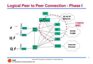
Network Interface Card Network Interface Card The Technicians Best Friend Antenna Tower Interference Analyzer E1 Tester Transmit and Receive simultaneously Local and Remote Loop Back BER, FER testing dBdsx Spectrum Analyzer 64 Kb/s, Voice Channels Channel Scanner Transmission Measurement Switch Center Cell Site RF Measurements Demodulation OTA GSM/GPRS/EDGE WCDMA/HSDPA WiMAX Backhaul BTS T1/E1 Transmitter Channel Service Unit Receiver Cable and Antenna Analyzer Return Loss Cable Loss DTF Power Meter/Monitor
Cable/Antenna Problems • Problems in the system, such as connector transitions, jumpers, kinks in the cable or moisture intrusion • Of all cable and antenna system problems • 60% are connector related • 20% are cable related • 5% are antenna related • The BTS Master includes Anritsu Site Master capabilities which is the de-facto industry standard for these measurements
Cable and Antenna Measurements • The measurements • Return Loss • Cable loss • Distance To Fault (DTF) • 2 Port Gain (TMA/LNA) • 2 Port Loss (Duplexer/Diplexer) • Precision Calibration • OSL Cal • Standard open, short, load • Flex Cal • No recalibration required
BTS Master TrainingIntroduction to Line Sweeping - RF Basics • The goal of a wireless communications system is to transfer the maximum amount of RF energy in one direction to achieve desired coverage • Garden hose and sprinkler • To accomplish this, a wireless communications system must “Match” from an RF standpoint • Otherwise, reflections occur • Reflections affect the overall performance of our system
BTS Master TrainingIntroduction to Line Sweeping - RF Basics • What do we mean by “Match” • In a RF/Wireless communications system, it is often necessary to connect various components together to deliver the signal from the transmitter/radio to the antenna • Cables, connectors, adapters, etc. • Each of the components within the system must match “electrically” (typically 50 ) as we are in essence transferring electrical energy • 75 50
BTS Master TrainingIntroduction to Line Sweeping - RF Basics • What do we mean by reflection? Signal Power From Source = Pi Pi Pr Reflected Power is Proportional to Impedance Mismatch Impedance Not Matched, Not 50 Ohms Reflection Coefficient = = Pr / Pi Expressed in Voltage Terms, = Er / Ei
BTS Master TrainingIntroduction to Line Sweeping - RF Basics • How can we tell if our system has a reflection or is not meeting specified performance? • Two types of measurements • VSWR Measurement • Return Loss Measurement VSWR and Return Loss Measurements provide a quick pass/fail measurement of a wireless system.
BTS Master TrainingIntroduction to Line Sweeping - RF Basics • Comparison of VSWR and Return Loss
BTS Master TrainingIntroduction to Line Sweeping - RF Basics • Common VSWR and Return Loss Values VSWR RL (dB)Component 1.5:1 -14 Antenna 1.22:1 -20 Lightning Arrestor 1.06:1 -30 Connector 1.01:1 -45 Cable
BTS Master TrainingLine Sweeping Fundamentals • In all, there are six measurements that provide the information required to verify the integrity of the transmission line or cable and antenna system • Cable Loss (Insertion Loss) of the transmission line. (1) • With an open or short connected • Return Loss / VSWR of the transmission line (3) • With a 50 Ohm termination connected • Return Loss / VSWR of the transmission line (5) • With Antenna connected • DTF-RL/ DTF-SWR of the transmission line (2) • With an open or short connected. • DTF-RL/ DTF-SWR of the transmission line (4) • With a 50 Ohm termination connected. • DTF-RL/ DTF-SWR of the transmission line (6) • With an Antenna connected.
BTS Master TrainingLine Sweeping Fundamentals • Must have three pieces of information to properly conduct a line sweep 1. Frequency Range • This can be determined from your system specs • Make sure that your antenna matches the specified frequency range 2. Cable Type(s) • This can be determined from your system specs • Make sure that your cable(s) match the specified cable type 3. Distance of Cable Run • This is not always outlined in your system specs, but is important • For less experienced line sweepers, it is suggested that you draw out the system before conducting a line sweep
BTS Master -Cable and Antenna AnalysisMeasurement Setup • Select the Shift key, then the Mode (9) key, using rotary knob or up/down arrow keys select Cable & Antenna Analyzer and press the Enter key to select. • Press the Freq/Dist function hard key. • Press the Start Freq soft key and enter the desired start frequency manually then press the Stop Freq and enter the desired stop freq, or press the Signal Standard soft key and select the applicable standard. • Select the Measurement hard key to select the desired measurement • VSWR • Return Loss • Cable Loss • DTF Return Loss • DTF VSWR • 2-Port Gain • Calibrate BTS Master
BTS Master -Cable and Antenna AnalysisMeasurement Setup – Calibration Procedure • Select the Shift key, then the Calibrate (2) key, using soft key select Cal Type 1-Port or 2-Port. The selected Cal Type will be underlined. • Select 1 port for RTN Loss and DTF Measurements • Select 2 port for testing gain and insertion loss of TMAs and Duplexers • Select Cal Power – High or Low. The selected Cal Power will be underlined. • 1 port measurements, low power is the only selection. • 2 port measurements, low power or high power can be selected. • Select low power for testing active devices such as TMAs. • Select high power for testing passives devices such as cables and filters. • Select Start Cal soft key to start calibration. • Follow instructions provided on the display of the BTS Master. • For two port calibrations two loads and two phase stable cables are required.
BTS Master -Cable and Antenna AnalysisSetting Limit Lines and Markers • Setting Limit Lines • Select the Shift key, then the Limit (6) key, using soft key select Limit Upper or Limit Lower. The selected Limit Type will be underlined. • Select Limit Edit soft key to set limit. Both an upper and lower limit can be set separately. • Select Limit On/Off soft key. Limit state will be underlined. • Setting Markers • Select Marker hard key to display marker menu. • Select Marker soft key to choose marker number. Chosen Marker will be underlined. • Selected marker will appear in Red on the display and can be adjusted using the daisy wheel. • Non selective markers will appear in Green on the displayand can not be adjusted.
BTS Master -Cable and Antenna AnalysisMeasurement Setup – Saving/Recalling Setups Saving Setup • Select the Shift key, then the File (7) key, using soft key select Save. • Select Directory Management soft key. • Select Current Location soft key to select data storage location. • Int. – Data stored to internal memory of BTS Master • USB – Data stored to external USB storage device. • CF – Data stored to compact flash drive. • Select Back soft key to return to previous page. • Select Save Setup soft key to save setup. • Use the daisy wheel or soft keys to name setup. • Select the Shift key, then the File (7) key, using soft select Recall. Recalling Setup • Select Recall soft key, then highlight desired setup for recall. • Select Recall soft key to recall setup.
BTS Master Return Loss Measurement Select RTN Loss Measurements from Measurement Menu RTN Loss with Load RTN Loss with Antenna
BTS MasterDTF Measurement Procedure • Press Measurement hard key • Select DTF RTN Loss soft key • Press Freq/Dist hard key • Select Cable soft key and choose the appropriate cable from the cable list. Press Enter Key • Select the Stop Dist soft key and enter the estimated distance of the transmission system • Press the More soft key to enter unit preference – meter or ft.
BTS MasterDistance to Fault Measurement DTF with Open DTF with Antenna
TMA Measurement • Tower Mounted Amp/Masthead Amplifiers Testing • On Tower Testing-RTN Loss • By Pass Circuitry- AMP in By Pass Mode • No By- Only TX Band will be swept • Pre-installed TMA Testing • Two port gain measurement
TMA MeasurementsTypical TMA Configurations • Simplex Configuration • Used in antenna systems that have separate RX and TX antennas and separate feed lines to the base station. • Single Duplex Configuration • Used in antenna systems that have a common RX and TX antenna and separate feed lines for the RX signal and TX signal to the base station. • Dual Duplex Configuration • Used in antenna systems that have both a common RX and TX antenna and a common transmission line to the BTS.
TMA MeasurementsBTS Master Set-up Procedure – TMA Gain • Testing TMA Prior to Installation (Two Port Gain) • Press the blue Shift key then press the Mode (#9) key then select Cable and Antenna Analyzer. • Press the Measurement hard key then select 2-port Gain. • Press Freq/Dist hard key then select Start Freq soft key to set the start freq next select Stop Freq soft key to set stop frequency. • Press the blue Shift key then press the Cal (#2) key. Set Cal Type to 2-port and set Cal Power to Low. Start Calibration. • Connect the RF Out port of the BTS Master to the Antenna port of the TMA and connect the RF In port to the BTS port of the TMA. • Press the Shift key then press the Sweep (#3) key, then select Bias Tee soft key. Set the required Bias Tee Voltage (+12 to +24), then set the Bias Tee to On. • Press the Shift key then press the Sweep (#3) key, then select Bias Tee soft key. Set the required Bias Tee Voltage (+12 to +24), then set the Bias Tee to On.
TMA MeasurementsInterpreting TMA Gain Measurement • 10 to 12 dB Gain in RX Band • Check Manufactures Spec • Reference Level equals 0 dB • Green Line • Bias T On – Top Slide • Bias T Off – Bottom Slide
BTS Master BTS Power Measurements • High Accuracy Power Meter • PSN50 • .16 dB of Accuracy • 50 MHz to 6 GHz freq • -30 dB to +20 dB • USB Interface • Internal Power Meter • .5 dB Accuracy • No External Power Head
Cable & Antenna Measurements Return Loss/VSWR
Cable & Antenna Measurements Distance to Fault Return Loss/VSWR 2 Port Gain Cable Loss
Cable & Antenna Measurements Distance to Fault Return Loss/VSWR 2 Port Gain Cable Loss
Base Station Transmit Receive BTS Master Basic Transmitter Measurements • For basic measurements the BTS Master will be directly connected to the base station. (connect directly to RF out with an attenuator or use Test/Monitor connector) • Use a 30 or 40 dB attenuator on RF output
GSM/EDGE RF/Demod Measurements • RF measurements • Spectrum display • Pass/Fail Slot Timing Mask • Complete Frame view • Demodulation measurements • Demodulation display • GSM, GMSK • EDGE, 8PSK • EVM • Phase Error • Carrier to Interference • Pass/Fail mode • Create custom test sets
BTS Master GSM/EDGE Measurements - Setup • Select the Shift key, then the Mode (9) key, using rotary knob or up/down arrow keys select GSM/GPRS/EDGE Signal Analyzer and press the Enter key to select. • Press the Freq function hard key. • Press the Center Freq soft key and enter the desired frequency manually, or press the Signal Standard soft key and select the applicable GSM standard. • Select the Channel soft key and use the Up/Down arrow keys, the keypad, or the rotary knob to select a channel number for the selected signal standard. The center of the channel is tuned to the center of the display. • Press the Setup function hard key. • Press the GSM/EDGE Auto to automatically select the GSM or EDGE signal. • Press the Amplitude hard key to set the power offset. • In put Power OffSet when external attenuator is used. • Set Auto Range to ON. BTS Master will automatically adjust attenuation.
BTS Master SM/EDGE Measurements – Setup • Press the Select Reference Frequency soft key to display a list of the available reference frequencies and select the desired reference frequency to get accurate frequency measurements as described in the previous section or Activate the GPS to get High Accuracy frequency error measurements. GPS Setup • Install the Anritsu GPS antenna to the GPS antenna connection on the BTS Master connector panel. • Select the Shift key, then the Mode (8) key. • Select GPS soft key to view GPS settings. • Select GPS On/Off to activate the GPS. Selected state will be underlined. • Select the GPS Info key to view the GPS information. • Number of Tracked Satellites • Latitude • Longitude • Altitude • Select the Measurement hard key to select the desired GSM Measurement.
GSM/GPRS/EDGE Measurements • MT8222A offers two GSM/GPRS/EDGE measurements that will each be addressed separately in the following guide: • GSM/GPRS/EDGE RF Measurements, with the MT8222A connected directly to the base station or to an antenna • GSM/GPRS/EDGE Demodulator Measurements, with the MT8222A connected directly to the base station or to an antenna.
GSM/GPRS/EDGE RF Measurements • GSM RF measurements are useful to quickly view the RF signal characteristics of the GSM carrier • GSM RF Measurements consist of: • Spectrum Measurements • GSM Channel Spectrum • Multi-channel measurements • Power versus time (frame), • Power versus time (slot)
The GSM Channel Spectrum and multi-channel measurements. Include: Channel Power Occupied Bandwidth Burst Power Frequency Error Modulation Type (GMSK for GSM and 8PSK for EDGE) Training Sequence Code (TSC) Channel Spectrum Key Strokes Press the Measurements function hard key. Press the Spectrum soft key to activate the spectrum measurement Select Channel spectrum for a single channel view or Mutli-channel spectrum key to display the multiple channels in a 2MHz span GSM/EDGE Channel Spectrum
The GSM Power versus Time Frame shows the 8 GSM time slots bursts or the combined EDGE time slots and GSM voice time slots bursts. . Include: Channel Power Occupied Bandwidth Burst Power Frequency Error Modulation Type (GMSK for GSM and 8PSK for EDGE) Training Sequence Code (TSC) Power versus Time (Frame) Key Strokes Press the Measurements function hard key. Press the Power vs. Time (Frame) soft key to activate the Power vs. time Frame measurement. GSM/EDGE Power Versus Time (Frame)
The GSM/EDGE Power vs. Time Slot shows: Single GSM/EDGE timeslot with a mask The rise and fall of the timeslot are the vertical signal traces within the mask The top flat section is the data burst. It is very important that the rise and fall of the timeslot falls within the mask, if there is too much variation then timeslot collisions may occur, causing degraded signal quality. Power versus Time (Frame) Key Strokes Press the Measurements function hard key. Press the Power vs. Time (Slot) soft key to activate the Power vs. time Slot measurement. GSM/EDGE Power Versus Time (Slot)
GSM/GPRS/EDGE demodulator demodulates the GSM/GPRS/EDGE signal and displays a constellation diagram showing the Phase and Amplitude vector changes in a graphical display. The GSM/GPRS/EDGE demodulator measurement displays: Phase error, Error Vector Magnitude (EVM) - (EDGE only) Origin Offset (EDGE only), Carrier to Interferer (C/I) - (EDGE only) Modulation type Magnitude error GSM and GPRS GMSK modulation EDGE uses 8PSK modulation GMSK modulation only has a Phase Shift vector parameter, the constellation diagram it looks like a ring 8PSK modulation has both a Phase Shift and Amplitude Shift for it’s vector parameters, in the constellation diagram EDGE tends to look like a plate of spaghetti Demodulator Key Strokes Press the Measurements function hard key. Press the Demodulator soft key to activate the Demodulator measurement. GSM/GPRS/EDGE Demodulator
GSM/GPRS/EDGE/TDMA RF Measurements RF Spectrum Power vs Time Slot with Mask Demodulation Display Power vs Time Frame
GPS • GPS hardware • Provides location information (longitude, latitude, altitude) for storage with traces. • Required for high accuracy frequency error measurements when measuring Over-The-Air. • High Accuracy measurements • Standard Accuracy: 0.3 ppm • GPS Accuracy: < 0.025 ppm • High Accuracy: < 0.025 ppm, <24 Hrs after GPS disconnect < 0.05 ppm, <72 Hrs after GPS disconnect GPS info display GPS Info Display Typical Performance Note: 3GPP standard +0.05 ppm +12 Hz – 0.05 ppm –12 Hz
Spectrum Analyzer • Wide Frequency Range • Specified 100 kHz to 7.1 GHz • Usable down to 9 kHz • Low Phase Noise • -100 dBm/Hz @ 10 kHz offset • Low Displayed Average Noise Level (DANL) • -153 dBm typical @ 1 GHz in 10 Hz RBW • Wide Dynamic Range • >80 dB Real Spectrum Analyzer performance without compromise Capabilities and Specification comparable to Bench Top solutions
Applications To find intermittent interference To identify and locate an interferer To measure the signal strength over time Measurements Spectrogram Spectrogram allows engineers and technicians to identify intermittent interfering signals that cause dropped calls Can measure a signal down to -153 dBm Save data up to 72 hours Signal Strength Locate an interfering signal based on signal strength RSSI Measure signal strength over time Measure the signal up to 72 hours Interference Analyzer Spectrogram Signal Strength
Base Station Transmit Receive BTS Master Power Measurements • For power measurements the BTS Master will be connected to the base station directly. (connect directly to RF out with an attenuator or use Test/Monitor connector) • Use a 30 or 40 dB attenuator on RF output
Power Measurements • Power Meter (base model) • Channelized power meter • Only measure actual channel • Based on spectrum analyzer circuitry • Calculated from real shape • No external probe required • Pass/Fail view • Set Pass/Fail tolerance • Easy Red or Green display • Power Monitor (Option) • For Microwave Backhaul • Broadband power • Can measure power up to 50 GHz • Needs external detector Power Meter Power Monitor Power Monitor is mutually exclusive with T1/E1 option
Applications Measure multiple channels transmitted signals power Easy setup for channel equalization Precise channel leveling improves system performance Easy Uplink, Downlink view Display Display 20 channels power as bar graphs or in table format Sequential Scan Stepped Channel Scan Custom Scan Uplink/Downlink Scan Max Hold See Max hold of each channel Display either current or max value Channel Scanner
Network Interface Card Network Interface Card Bit Error Rate Measurements • For T1 measurements the BTS Master will be connected to the base stations Network interface directly. (direct connect for Testing or Monitoring) BTS Master Base Station Switch Center Backhaul T1/E1 Transmit Receive Channel Service Unit
Test Mode Test Mode Tx Tx Rx Rx DS1 DS1 H H H H DS1 DS1 AUTO AUTO Alarm On Alarm On Signal Signal Alarms Alarms Error On Error On Frame Sync Frame Sync Errors Errors Line Code Line Code Loop On Loop On Pattern Sync Pattern Sync B8ZS B8ZS B8ZS B8ZS DS1 DS1 Signal Setup Signal Setup Tx Tx Clock Clock DS1 DS1 Test Mode : Test Mode : Internal Internal B8ZS B8ZS Line Code : Line Code : Rx Level Rx Level Terminate Terminate Internal Internal Tx Tx Clock : Clock : Framing Framing 0dB 0dB Tx Tx LBO : LBO : ESF ESF Terminate Terminate Rx Input : Rx Input : Payload Payload 1.544Mb 1.544Mb ESF ESF Framing : Framing : Pattern Pattern PRBS PRBS - - 23 23 Error/Alarm Error/Alarm Bit Bit Loop Code Loop Code Line Data Link Line Data Link Measurements Measurements Start/Stop Start/Stop Pattern/Loop Pattern/Loop Error/Alarm Error/Alarm Configuration Configuration Test Mode Test Mode Tx Tx Rx Rx DS1 DS1 H H H H DS1 DS1 BERT BERT Alarm On Alarm On Signal Signal Alarms Alarms Ch Power ( Ch Power ( dBm dBm ) ) Error On Error On Frame Sync Frame Sync Errors Errors Line Code Line Code Loop On Loop On Pattern Sync Pattern Sync B8ZS B8ZS B8ZS B8ZS BERT BERT VF VF Tx Tx Clock Clock Internal Internal Rx Level Rx Level Terminate Terminate - - - - 6.0dB 6.0dB 6.0dB 6.0dB Framing Framing ESF ESF Results OK Results OK Payload Payload 64Kb 64Kb Pattern Pattern PRBS PRBS - - 9 9 Measurement Measurement Time Time Manual Manual Error/Alarm Error/Alarm Bit Bit Clear Clear PATL PATL Loop Code Loop Code History History Line Data Link Line Data Link Start Time = 03.00.00 Start Time = 03.00.00 - - 12.31.06 12.31.06 Rx = 6.5 Rx = 6.5 Vpp Vpp ( 0.8 ( 0.8 dBdsx dBdsx ) ) Save Results Save Results Measurement Time = Manual Measurement Time = Manual Elapsed Time = 3 hr 59 min 10 sec Elapsed Time = 3 hr 59 min 10 sec Measurements Measurements Start/Stop Start/Stop Pattern/Loop Pattern/Loop Error/Alarm Error/Alarm Configuration Configuration T1/E1 Measurements • Capabilities • Carrier, frame sync and pattern sync have color LED indicators. • Frequency of the E1 or T1 carrier is displayed • Make BERT measurements • Histogram display for fault correlation • Send Loop codes • Can listen to VF channels • Analyzer ITU-T G.821 analysis • Errored seconds • Severely errored seconds • Unavailable seconds • Available seconds • Error free seconds • Degraded minutes
PC and LAN connectivity • The MT8222A includes the Master Software Tool program for management of all results on the PC • The BTS Master has both USB and Ethernet connectivity easy retrieval of results data • The Flash Memory Card (included) can store 64Mbyte of data Base Station BTS Master Transmit Receive
Master Software Tools 1 • Easy access to traces/results • 2000 plus stored results in instrument • The user can • View multiple traces/results • Zoom into a trace in both amplitude and frequency • Overlay traces on one graph • Save traces/results on computer • GPS support with maps • Requires Microsoft Map point program • View Map with GPS info and Data • Report Feature • All the measurement parameters are listed • Export graphic files for use in other programs • Export text data files for use in spreadsheets • Print graphs on any local or network printer