Download
1 / 56
560 likes | 957 Vues
AMS-02 Thermal Control System (TCS). AMS-02 Thermal Overview. AMS-02 delivered to ISS in orbiter payload bay Mounted on S3, inboard, zenith Payload Attach Site Payload nominally dissipates 2400 watts (2800 watts peak) Will meet all ISS and STS safety requirements

E N D
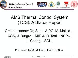
AMS-02 Thermal Control System (TCS) AMS-02 Phase II Safety Review
AMS-02 Thermal Overview • AMS-02 delivered to ISS in orbiter payload bay • Mounted on S3, inboard, zenith Payload Attach Site • Payload nominally dissipates 2400 watts (2800 watts peak) • Will meet all ISS and STS safety requirements • Thermal requirements are defined in SSP 57003 (Attached Payload Interface Requirements Document) • Thermal Design Goals • Maintain all experiment components and sub-detectors within specified operating and survival limits (document in AMS-02 Thermal ICD) • Maximize Super Fluid Helium (SFHe) endurance • Optimize sub-detector temperatures to maximize science AMS-02 Phase II Safety Review
AMS-02 TCS Hardware • Radiators • Heaters • Thermal Blankets • Loop Heat Pipes (LHPs) • Standard Axial Groove Heat Pipes • 2-Phase CO2 pumped loop • Surface Optical Coatings AMS-02 Phase II Safety Review
Radiators • AMS-02 radiators include Main Radiators (Ram and Wake), Tracker Radiators (Ram and Wake), and Zenith Cryocooler Radiators. Wake Ram Main Radiator Wake Main Radiator Ram AMS-02 Phase II Safety Review
Main Radiators • Main Radiators dissipate heat from electronics crates. • Ram radiator dissipates up to 525 watts during normal operation, while the Wake Radiator dissipates up to 812 watts. AMS-02 Phase II Safety Review
Main Radiators Mounting • Main Radiators are mounted to directly to the crates, which in turn are attached to the USS-02 Upper Brackets (4) Mid Bracket (4) Lower Brackets (4) AMS-02 Phase II Safety Review
Main Radiator Construction • Radiators are a sandwich construction with Al face sheets and a ROHACELL® core. • Axial groove heat pipes (aluminum filled with ammonia) are imbedded between face sheets. • Heat pipe flanges maximize thermal contact at crates mounting locations • Chotherm 1671 is used as a thermal interface filler between crates and radiators. • Radiators are painted with SG121FD white paint to optimize heat rejection. AMS-02 Phase II Safety Review
AMS-02 Main Radiator Cross-section (flange removed) AMS-02 Phase II Safety Review
AMS-02 Main Radiator Heat Pipe Layout Ram Wake AMS-02 Phase II Safety Review
Tracker Radiators • Ram and Wake Tracker Radiators are designed to reject the total heat generated inside the Tracker (144W). • Heat is transported by the Tracker Thermal Control System (TTCS) which will be discussed latter. AMS-02 Phase II Safety Review
Tracker Radiators Tracker Radiator (2 x 1.225 m2) AMS-02 Phase II Safety Review
Tracker Radiator Construction • Tracker Radiators are a sandwich construction with Al face sheets and a ROHACELL® core. • Heat pipes (aluminum filled with ammonia) are imbedded between face sheets. • TTCS Condensers bolt directly to heat pipe flanges (40mm wide at interface locations, but only 22mm elsewhere). • Chotherm 1671 is used as a thermal interface filler between condensers and radiators. • Outer surface is painted with SG121FD white paint to optimize heat rejection. AMS-02 Phase II Safety Review
Tracker Radiator Cross-Section (non-interface section) AMS-02 Phase II Safety Review
TTCS Condenser Mounting Interface AMS-02 Phase II Safety Review
Tracker Radiator Heat Pipe Layout AMS-02 Phase II Safety Review
EMBEDDED HEAT PIPE RADIATOR PANEL CARBON FIBER SUPPORT STRUTS TTCS CO2 CONDENSERS (old design) AMS-02 Phase II Safety Review
Zenith Radiator • The Zenith Radiator (4 separate panels) is design to reject the waste heat generated by the Cryocoolers (60-160W each). • Heat is transported to each radiator panel via 2 Loop Heat Pipes (LHPs) attached to a single cryocooler. • The LHPs utilize propylene as a working fluid which flows directly through aluminum tubes embedded in the Radiator. • Aluminum tubes in the radiator transition to stainless steel tubes running to the evaporator via a bi-metallic joint. AMS-02 Phase II Safety Review
Zenith Radiator Panels AMS-02 Phase II Safety Review
Zenith Radiator Construction • Radiators are a sandwich construction with Al face sheets and a ROHACELL® core. • 3mm aluminum tubes are brazed to upper face sheet. • Radiator panels are mounted to top of TRD Upper Honeycomb Panel via brackets and glass-fiber pins. • Outer surface is coated with silver-Teflon. • Multi-layer Insulation (MLI) is used between Radiator and TRD. AMS-02 Phase II Safety Review
Zenith Radiator Cross-Section Radiator Mounting Radiator Cross-section AMS-02 Phase II Safety Review
Multi-Layer Insulation (MLI) Blankets AMS-02 Phase II Safety Review
Multi-Layer Insulation (MLI) Blankets • Numerous components of AMS-02 will be covered with MLI blankets • All blankets will meet NASA standards for grounding and venting, and will be constructed according to “MLI for AMS Guidelines” (CTSD-SH-1782) • All blankets will be positively secured. • Typical construction will include multiple layers of aluminized Mylar separated by Dacron scrim. Betacloth will protect exposed surfaces. AMS-02 Phase II Safety Review
MLI for AMS Guidelines • Written by Crew and Thermal Systems Division (CTSD-SH-1782, September 30, 2005) • Based on requirements from ISS, STS and MSFC • Electrical Bonding and Grounding • All blankets with surface area greater than 100cm2 will have at least two (2) grounding assemblies. • Resistance from aluminized surface to ground shall be less than (<) 5,000 Ohms • Resistance from ground to spacecraft structure shall be less than (<) 1 Ohm AMS-02 Phase II Safety Review
Heaters • Heaters on AMS-02 are primarily used to: • Warm up components to “switch on” temperature after power outages (including initial turn-on). • Maintain components above minimum operating limits during operation. • Thaw CO2 (TTCS system) and NH3 (heat pipes) in case of extended power outages in cold environments. • Manage TTCS operation AMS-02 Phase II Safety Review
Heaters (continued) • Most heaters are both thermostatically and computer controlled. • Analyses have been performed to evaluate effect of “run away” heaters. • All safety critical heaters are two-fault tolerant. • No heaters are required to control any hazards. AMS-02 Phase II Safety Review
Heat Pipes • Standard axial groove heat pipes are used in several location to help distribute heat: • Main and Tracker radiators have embedded heat pipes mounted directly to heat sources. • Heat pipes are mounted to one of the USS-02 joints to help dissipate heat from the CAB during magnet charging. • Heat pipes are used on the CAB base plates to minimize gradients. • All heat pipes are aluminum filled with high purity ammonia. • Heat pipes are designed to survive freezing/thawing cycles without excessive pressure or rupture. AMS-02 Phase II Safety Review
Thermal Optical Coatings • Passive thermal design of AMS-02 include the use of thermal optical coatings. • MLI blankets or plain Betacloth covers are used to improve optics of some surfaces. • Main and Tracker radiators are painted with SG121FD white paint to improve heat rejection. • The Zenith Radiator, along with parts of the Vacuum Case, USS-02, High Voltage Bricks, and CAB are covered with silver-Teflon film to reduce peak temperatures. AMS-02 Phase II Safety Review
Cryocooler Cooling • Each of the 4 Cryocoolers dissipate up to 160W of heat in order to remove 4 – 10W of heat from the Cryomagnet system. • Loop Heat Pipes (2 per Cryocooler) are used to transport this heat to the Zenith Radiator where it is rejected via radiation. • The Loop Heat Pipes (LHPs), provided by IberEspacio/Madrid, are similar to those successfully demonstrated as part of COM2PLEX flown on STS-107. • Propylene is used as a working fluid to avoid any freezing. Freezing point of propylene is -185C. AMS-02 Phase II Safety Review
Loop Heat Pipe System for 1 Cryocooler Radiator panel Fluid Lines Redundant Evaporators AMS-02 Phase II Safety Review
LHP Configuration • Each LHP has a vapor line running to the Zenith Radiator and a liquid line returning. • Lines in and out of the evaporator are stainless steel tube. These tubes transition to aluminum tubes at the edge of the Zenith Radiator via a bi-metallic joint. • “Pumping” pressure is achieved via capillary action in the LHP wick (nickel). AMS-02 Phase II Safety Review
LHP Schematic AMS-02 Phase II Safety Review
Crycooler to LHP Interface • LHP Evaporators bolt to either side of the Cryocooler heat reject collar. • Indium foil is used as a thermal interface. Cryocooler Evaporator AMS-02 Phase II Safety Review
LHP Heaters • Heaters are mounted to the evaporators for LHP startup and to keep Cryocoolers above their minimum storage limits. AMS-02 Phase II Safety Review
LHP Bypass Valve • A bypass valve is used to keep Cryocoolers from getting too cold in power outage situations. • A bellows system filled with Argon is used to set the temperature set point of the valve. AMS-02 Phase II Safety Review
LHP Bypass Valve Schematic (Argon) AMS-02 Phase II Safety Review
CAB Thermal System • The Cryomagnet Avionics Box (CAB) is used to monitor and control the Cryomagnet. • Heat dissipation can vary from 35W to 800W. • Two Loop Heat Pipes (LHPs) will transport heat from the CAB base plate to the outer skin of the Wake Radiator. • Final design details are under review. AMS-02 Phase II Safety Review
CAB Thermal System • LHP are similar to Cryocooler LHPs, except that ammonia, rather than propylene will be used as the working fluid. • A bypass valve on the LHP will be used to bypass the radiator if CAB temperature approach lower limits. AMS-02 Phase II Safety Review
CAB Thermal System CAB AMS-02 Phase II Safety Review
CAB Thermal System • Additional axial groove heat pipes will be attached on the USS between the Upper Trunnion Bridge Beam and the Upper Vacuum Case Interface Joint. AMS-02 Phase II Safety Review
TRD Thermal Design • The TRD must be isothermal to +/-3ºC • The TRD and Upper Time Of Flight (UTOF) are enclosed in a common thermal enclosure made of MLI blankets. • The Zenith Radiator is mounted on top of the TRD using low conductivity pins. • Primary TRD interfaces to USS-02 joints are insulated with titanium spacers. AMS-02 Phase II Safety Review
TRD Thermal Design Zenith Radiator TRD UTOF AMS-02 Phase II Safety Review
TRD Thermal Design • The MLI blanket enclosure is made of 7-layer MLI, except for the portion under the Zenith radiator which is 10-layer. • Heaters are mounted on the TRD M-structure to help minimize gradients and to maintain the detector components (flipper valves) within operating limits. AMS-02 Phase II Safety Review
TRD MLI M-structure AMS-02 Phase II Safety Review
TRD Gas Thermal Design • The TRD Gas system consists of two parts; the Supply (Box S) and the Circulation (Box C). • Box S includes a high pressure Xenon tank, a high pressure CO2 tank, a mixing tank, pre-heater volumes, valves, pressure sensors, and associated tubing all mounted on an aluminum base plate. • Box C includes two pumps, monitoring tubes and valves. • Both Box S and Box C are enclosed in an MLI blanket. AMS-02 Phase II Safety Review
TRD Gas Thermal Design Circulation Box (Box C) Xe Tank Valve blocks CO2 Tank AMS-02 Phase II Safety Review
TRD Gas Tank Heaters • Active heating is required to keep both the Xenon and CO2 tanks above their respective saturation temperatures. • This is required in order to measure the amount of gas left in the tanks. • Extremely long time constants preclude short term heating only. • The Xenon tank should stay above 20ºC • The CO2 tank should stay above 34ºC AMS-02 Phase II Safety Review
TRD Gas Tank Heaters • Kapton foil heaters are glued to the surface of the composite over-wrapped stainless steel tanks. • On each tank there are two strings of eight heater patches (one per power feed). • Four thermostats in series are used for each string to protect against over heating the tanks. • Each tank is wrapped with MLI. AMS-02 Phase II Safety Review
TRD Gas Tank Heaters heaters thermostats AMS-02 Phase II Safety Review
TRD Gas Pre-Heaters • A Pre-heater is used to warm small volumes of Xenon and CO2 making transfer to the mixing tank more controlled. • Heater is computer controlled using temperature sensors on heater plate. • Heater will only be activated for brief periods (<15 minutes per day) • 4 thermostats in series protects against over heating. AMS-02 Phase II Safety Review
TRD Gas Valve Blocks • The are 5 groups of valves in Box S mounted together with support brackets. • Brackets are isolated from the base plate with G10 spacers. • Each block of valves is individually wrapped with MLI. • Resistive heaters are mounted on each valve support bracket to maintain valves above operating limits. • A single thermostat is used to control each valve block heater (Except for the tower valve which has 4 in series) • Two additional thermostats in series are mounted on the base plate to control power to all valve heaters. AMS-02 Phase II Safety Review