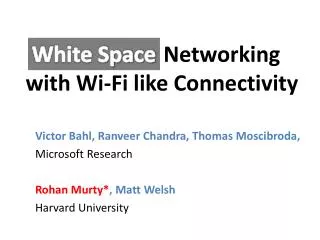
Next Generation Wi-Fi: Networking over White Spaces
390 likes | 567 Vues
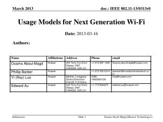
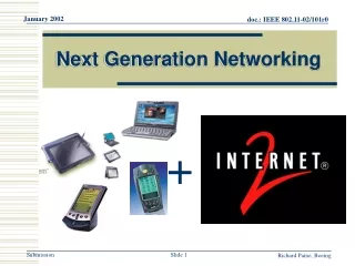
Next Generation Wi-Fi: Networking over White Spaces. Ranveer Chandra Collaborators: Victor Bahl, Thomas Moscibroda, Srihari Narlanka, Yunnan Wu, Yuan Yuan. Wi-Fi’s Success Story. Wi-Fi is extremely popular (billion $$ business) Enterprise/campus LANs, Home networks, Hotspots

Next Generation Wi-Fi: Networking over White Spaces
E N D
Presentation Transcript
Next Generation Wi-Fi:Networking over White Spaces Ranveer Chandra Collaborators: Victor Bahl, Thomas Moscibroda, Srihari Narlanka, Yunnan Wu, Yuan Yuan
Wi-Fi’s Success Story • Wi-Fi is extremely popular (billion $$ business) • Enterprise/campus LANs, Home networks, Hotspots • Why is Wi-Fi successful • Wireless connectivity: no wires, increased reach • Broadband speeds: 54 Mbps (11a/g), 200 Mbps (11n) • Free: operates in unlicensed bands, in contrast to cellular
Problems with Wi-Fi • Poor performance: • Contention with Wi-Fi devices • Interference from other devices in 2.4 GHz, such as Bluetooth, Zigbee, microwave ovens, … • Low range: • Can only get to a few 100 meters in 2.4 GHz • Range decreases with transmission rate
Overcoming Wi-Fi’s Problems • Poor performance: • Fix Wi-Fi protocol – several research efforts (11n, MIMO, interference cancellation, …) • Obtain new spectrum? • Low range: • Operate at lower frequencies?
The Silver Lining • Although spectrum is occupied, it is unused • White spaces: spectrum that is not in use by their licensed operators • Example: TV-Bands -60 “White spaces” dbm 750 MHz 470 MHz -100 Frequency
The White Space Ruling • On November 4th, 2008, FCC approved operation of unlicensed devices on TV channels • Unlicensed devices should not interfere with primary users (TV broadcasts, wireless microphones) • Devices should use spectrum scanning or geo-location database to determine presence of primary • TV channels available: from 7-13 (VHF) and 14-51 (UHF) • Portable devices can use channels 21 to 51 (182 MHz), transmit power of 40 mW.
Cognitive (Smart) Radios • Dynamically identify currently unused portions of spectrum • Configure radio to operate in available spectrum band take smart decisions how to share the spectrum Signal Strength Signal Strength Frequency Frequency
Challenges • Hidden terminal problem in TV bands 518 – 524 MHz 521 MHz interference TV Coverage Area
Challenges • Hidden terminal problem in TV bands • Maximize use of fragmented spectrum • Could be of different widths -60 “White spaces” dbm 750 MHz 470 MHz -100 Frequency
Challenges • Hidden terminal problem in TV bands • Maximize use of available spectrum • Coordinate spectrum availability among nodes Signal Strength Signal Strength Frequency Frequency
Challenges • Hidden terminal problem in TV bands • Maximize use of available spectrum • Coordinate spectrum availability among nodes • MAC to maximize spectrum utilization • Physical layer optimizations • Policy to minimize interference • Etiquettes for spectrum sharing
DySpan 2007, LANMAN 2007, MobiHoc2008 Our Approach: KNOWS Maximize Spectrum Utilization [MobiHoc’08] Coordinate spectrum availability [DySpan’07] Reduces hidden terminal, fragmentation [LANMAN’07]
Outline • Networking in White Spaces • KNOWS Platform – the hardware • CMAC – the MAC protocol • B-SMART – spectrum sharing algorithm • Future directionsand conclusions
Hardware Design • Send high data rate signals in TV bands • Wi-Fi card + UHF translator • Operate in vacant TV bands • Detect TV transmissions using a scanner • Avoid hidden terminal problem • Detect TV transmission much below decode threshold • Signal should fit in TV band (6 MHz) • Modify Wi-Fi driver to generate 5 MHz signals • Utilize fragments of different widths • Modify Wi-Fi driver to generate 5-10-20-40 MHz signals
Operating in TV Bands DSP Routines detect TV presence Scanner UHF Translator Wireless Card Set channel for data communication Modify driver to operate in 5-10-20-40 MHz Transmission in the TV Band
Data Transceiver Antenna Scanner Antenna KNOWS: Salient Features • Prototype has transceiver and scanner • Use scanner as receiver on control channel when not scanning
KNOWS: Salient Features • Can dynamically adjust channel-width and center-frequency. • Low time overhead for switching (~0.1ms) can change at very fine-grained time-scale Transceiver can tune to contiguous spectrum bands only! Frequency
Changing Channel Widths Scheme 1: Turn off certain subcarriers ~ OFDMA 10 MHz 20 MHz Issues: Guard band? Pilot tones? Modulation scheme?
Changing Channel Widths Scheme 2: reduce subcarrier spacing and width! Increase symbol interval 10 MHz 20 MHz Properties: same # of subcarriers, same modulation
Adaptive Channel-Width 20Mhz 5Mhz • Why is this a good thing…? • Fragmentation White spaces may have different sizes Make use of narrow white spaces if necessary • Opportunistic, load-aware channel allocation Few nodes: Give them wider bands! Many nodes: Partition the spectrum in narrower bands Frequency
Outline • Networking in TV Bands • KNOWS Platform – the hardware • CMAC – the MAC protocol • B-SMART – spectrum sharing algorithm • Future directionsand conclusions
MAC Layer Challenges • Crucial challenge from networking point of view: How should nodes share the spectrum? Which spectrum-band should two cognitive radios use for transmission? Channel-width…? Frequency…? Duration…? Determines network throughput and overall spectrum utilization! We need a protocol that efficiently allocates time-spectrum blocks in the space!
Allocating Time-Spectrum Blocks • View of a node v: Frequency Primary users f+f f Time t t+t Time-Spectrum Block Node v’s time-spectrum block Neighboring nodes’time-spectrum blocks Within a time-spectrum block, any MAC and/or communication protocol can be used ACK ACK ACK
Context and Related Work • Context: • Single-channel IEEE 802.11 MAC allocates on time blocks • Multi-channel Time-spectrum blocks have fixed channel-width • Cognitive channels with variable channel-width! time Multi-Channel MAC-Protocols: [SSCH, Mobicom 2004], [MMAC, Mobihoc 2004], [DCA I-SPAN 2000], [xRDT, SECON 2006], etc… Existing theoretical or practical work does not consider channel-width as a tunable parameter! MAC-layer protocols for Cognitive Radio Networks: [Zhao et al, DySpan 2005], [Ma et al, DySpan 2005], etc… • Regulate communication of nodes • on fixed channel widths
CMAC Overview • Use common control channel (CCC) [900 MHz band] • Contend for spectrum access • Reserve time-spectrum block • Exchange spectrum availability information (use scanner to listen to CCC while transmitting) • Maintain reserved time-spectrum blocks • Overhear neighboring node’s control packets • Generate 2D view of time-spectrum block reservations
CMAC Overview • RTS • Indicates intention for transmitting • Contains suggestions for available time-spectrum block (b-SMART) • CTS • Spectrum selection (received-based) • (f,f, t, t) of selected time-spectrum block • DTS • Data Transmission reServation • Announces reserved time-spectrum block to neighbors of sender Sender Receiver RTS CTS DTS Waiting Time t DATA ACK DATA Time-Spectrum Block ACK DATA ACK t+t
Network Allocation Matrix (NAM) Nodes record info for reserved time-spectrum blocks Time-spectrum block Frequency Control channel IEEE 802.11-like Congestion resolution Time The above depicts an ideal scenario 1) Primary users (fragmentation) 2) In multi-hop neighbors have different views
Network Allocation Matrix (NAM) Nodes record info for reserved time-spectrum blocks Primary Users Frequency Control channel IEEE 802.11-like Congestion resolution Time The above depicts an ideal scenario 1) Primary users (fragmentation) 2) In multi-hop neighbors have different views
B-SMART • Which time-spectrum block should be reserved…? • How long…? How wide…? • B-SMART (distributed spectrumallocation over white spaces) • Design Principles B: Total available spectrum N: Number of disjoint flows 1. Try to assign each flow blocks of bandwidth B/N 2. Choose optimal transmission duration t Short blocks: More congestion on control channel Long blocks: Higher delay
B-SMART • Upper bound Tmax~10ms on maximum block duration • Nodes always try to send for Tmax 1. Find smallest bandwidth b for which current queue-length is sufficient to fill block b Tmax b b=B/N Tmax Tmax 2. Ifb ≥B/Nthenb := B/N 3. Find placement of bxt block that minimizes finishing time and does not overlap with any other block 4. If no such block can be placed due prohibited bands thenb := b/2
Example • Number of valid reservations in NAM estimate for N • Case study: 8 backlogged single-hop flows Tmax 80MHz 2(N=2) 4 (N=4) 8 (N=8) 2 (N=8) 5(N=5) 1 (N=8) 40MHz 3 (N=8) 1 (N=1) 3 (N=3) 7(N=7) 6 (N=6) 1 2 3 4 5 6 7 8 1 2 3 Time
B-SMART • How to select an ideal Tmax…? • Let be maximum number of disjoint channels (with minimal channel-width) • We define Tmax:= T0 • We estimate N by #reservations in NAM based on up-to-date information adaptive! • We can also handle flows with different demands (only add queue length to RTS, CTS packets!) TO: Average time spent on one successful handshake on control channel Nodes return to control channel slower than handshakes are completed Prevents control channel from becoming a bottleneck!
Performance Analysis In the paper only… • Markov-based performance model for CMAC/B-SMART • Captures randomized back-off on control channel • B-SMART spectrum allocation • We derive saturation throughput for various parameters • Does the control channel become a bottleneck…? • If so, at what number of users…? • Impact of Tmaxand other protocol parameters • Analytical results closely match simulated results Even for large number of flows, control channel can be prevented from becoming a bottleneck Provides strong validation for our choice of Tmax
Simulation Results - Summary • Simulations in QualNet • Various traffic patterns, mobility models, topologies • B-SMART in fragmented spectrum: • When #flows small total throughput increases with #flows • When #flows large total throughput degrades very slowly • B-SMART with various traffic patterns: • Adapts very well to high and moderate load traffic patterns • With a large number of very low-load flows performance degrades ( Control channel)
KNOWS in Mesh Networks More in the paper… Aggregate Throughput of Disjoint UDP flows Throughput (Mbps) b-SMART finds the best allocation! # of flows
Summary • White Spaces overcome shortcoming of Wi-Fi • Possible to build hardware that does not interfere with TV transmissions • CMAC uses control channel to coordinate among nodes • B-SMART efficiently utilizes available spectrum by using variable channel widths
Future Work & Open Problems • Integrate B-SMART into KNOWS • Address control channel vulnerability • Design AP-based networks • Build, demonstrate large mesh network!
Other Ongoing Projects • Network Management • DAIR: Managing enterprise wireless networks • Sherlock: localizing performance failures • eXpose: mining for communication rules in a packet trace • Green Computing • Cell2Notify: reducing battery consumption of mobile phones • Somniloquy: enabling network connectivity to sleeping PCs