Download
1 / 56
590 likes | 941 Vues
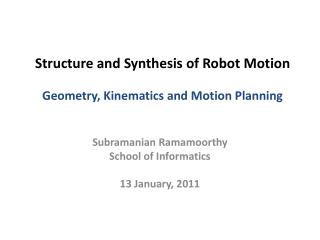
Structure and Synthesis of Robot Motion Introduction: Kinematics & Sampling-based Motion Planning. Subramanian Ramamoorthy School of Informatics 19 January, 2012. Describing Robot Motion. Different aspects to the description How does the robot move? How do we want to represent that?

E N D
Structure and Synthesis of Robot MotionIntroduction: Kinematics & Sampling-based Motion Planning Subramanian Ramamoorthy School of Informatics 19 January, 2012
Describing Robot Motion • Different aspects to the description • How does the robot move? How do we want to represent that? • Where does the robot move? How to represent environment? • Consider a walking robot: Can capture poses in a configuration space (a.k.a. joint space) Environment/constraints would shape the geometry in the work/task space Some dynamics information is better understood in phase space Structure and Synthesis of Robot Motion
The Configuration Space • A space describing the various configuration variables • In the example, there are two rotational joints (each variable evolves along a circle, S1 • Combined effect is that motion can be described as points on the torus 2p Elbow angle 0 2p Wrist angle Structure and Synthesis of Robot Motion
Relating C-Space and Workspace Note the change in obstacle ‘shape’ in going from one space to another. How do we efficiently compute this? Structure and Synthesis of Robot Motion
Configuration Spaces can be Complex Structure and Synthesis of Robot Motion
What is Kinematics? • Robot kinematics: In a kinematic analysis the position, velocity and acceleration of all links are calculated without considering forces that cause this motion. • As opposed to dynamics - which studies relation between motion of objects and its causes. • Robot kinematics deals with aspects of redundancy, collision avoidance and singularity avoidance. Structure and Synthesis of Robot Motion
Start from Basics: Simplest Example • Consider a 2-dim object on a plane, goes from one pose to another as shown: • To describe it (in a computer program), keep track of • Translation of a canonical point, say, the center – (x,y) • Angle by which object is rotated (with appropriate convention for axis and direction) - q • If I have many objects, I’ll need to pick a global origin and describe them all in terms of corresponding (x, y, q) Structure and Synthesis of Robot Motion
2-dim Motion • Such equations can describe two things: • Change of coordinate frames between points in robot • New position of an object if it performs a motion in the environment Structure and Synthesis of Robot Motion
2-dim Motion Structure and Synthesis of Robot Motion
Describing 3-dim motion Structure and Synthesis of Robot Motion
(Non)-commutativity In 3-dim (and beyond), interesting things begin to happen: You need to know the order of operations to be able to fully describe the result! Structure and Synthesis of Robot Motion
Combined 3-dim Rotations If a robot/object consists of many links/parts, we could compute position of any end with respect to a base via an appropriate sequence of transformations: Where are these two points w.r.t. each other? Structure and Synthesis of Robot Motion
A Question • Suppose you want to hold some things fixed in your robot while the rest of the mechanism does its thing… e.g., you want to hold a glass of water (hence your ‘end effector’ position) while moving the hand/glass to your mouth • This happens in many settings: • Constraint (wiping windows) • Dynamics (Do not fall/slip) • Task spec. (‘standing’ poses) Structure and Synthesis of Robot Motion
Describing Subspaces • The kind of restrictions in the previous slide correspond to subspaces • A linear subspace would be a hyperplane • In general, when we translate between spaces, the restrictions take on a more general form Structure and Synthesis of Robot Motion
A Typical Scenario • Many robotics problems involve a workspace goal that needs to be achieved through joint space actions • Translating between the two coordinate systems requires thinking through a sequence of coord. Frames • In the figure: • How does object motion translate to robot manipulator motion? Structure and Synthesis of Robot Motion
Two Aspects of Kinematics • Forward Kinematics • Given joint angles, compute the transformation between world & gripper coordinates • Relatively straightforward • Inverse Kinematics • Given the transformation between world coordinates and an arbitrary frame, compute the joint angles that would line your gripper coordinates up with that frame. • More involved than forward case, as will see Structure and Synthesis of Robot Motion
Forward Kinematics Scenario: You have a robotic arm that starts out aligned with the xo-axis. You tell the first link to move by q1 and the second link to move by q2 Question: What is the position of the end of the robotic arm? Solution: Use transformation matrices from earlier lecture Structure and Synthesis of Robot Motion
Locate the Yellow Dot in Base Frame Translation, along x2, by l2 H = Rz(1) * Tx1(l1) * Rz(2) * Tx2(l2) * Rz(3) i.e. Rotating by 1will put you in the X1Y1frame. Translate in the along the X1 axis by l1. Rotating by 2will put you in the X2Y2frame. and so on until you are in the X3Y3frame. The position of the yellow dot relative to the X3Y3frameis (l1, 0). Multiplying H by that position vector will give you the coordinates of the yellow point relative the the X0Y0frame. Y3 3 Rotation, around z, by Y2 2 3 X3 Y2 2 X2 Y0 1 X1 1 Y1 X0 Structure and Synthesis of Robot Motion
Variation: New Coordinate Frame at the Dot Y3 Y4 3 2 3 X3 Y2 2 X2 X4 H = Rz(1) * Tx1(l1) * Rz(2) * Tx2(l2) * Rz(3) * Tx3(l3) This takes you from the X0Y0 frame to the X4Y4 frame. The position of the yellow dot relative to the X4Y4 frame is (0,0). Y0 1 X1 1 Y1 X0 Notice that multiplying by the (0,0,0,1) vector will equal the last column of the H matrix. Structure and Synthesis of Robot Motion
Inverse Kinematics: Simplest Example Find Angle: Revolute and Prismatic Joints Combined More Specifically: (x , y) arctan2() specifies that it’s in the first quadrant Y S q1 Finding S: X Structure and Synthesis of Robot Motion
l2 l1 Bit More Complex: 2-link Manipulator (x , y) Given:l1, l2 ,x , y Find: q1, q2 Redundancy: A unique solution to this problem does not exist - two solutions are possible. Sometimes no solution is possible. q2 l2 l1 q1 (x , y) l2 l1 Structure and Synthesis of Robot Motion
Solving for the Joint Angles q l2 q2 (x , y) l1 q1 Structure and Synthesis of Robot Motion
Solving for Joint Angles, Contd. Structure and Synthesis of Robot Motion
Things Can Get Complicated… This is still within our model: But, we’d like to avoid tedious calculations like in last slide Hands should follow the mouse Keep feet fixed Structure and Synthesis of Robot Motion
Use of the Jacobian – Computing Velocities • Chain of links maps a set of input variables (Joint Angles) to end effecter variables: • The Jacobian is defined as: • A transformation from joint velocities to end-point velocities: Structure and Synthesis of Robot Motion
Jacobian: A Simple Example Structure and Synthesis of Robot Motion
Using the Jacobian Inverse • Use task level goals to figure out how end effecter should move - V • Solve for the joint angle velocities: • Some pitfalls: • J might be singular • Overdetermined system Concept of Pseudoinverse: Structure and Synthesis of Robot Motion
Jacobian of the 2-link Arm Structure and Synthesis of Robot Motion
Regularizing the Inverse • While the pseudoinverse will yield a solution, it may not be the right one always • What are the criteria? • One way to handle this is to define additional optimisation criteria: Structure and Synthesis of Robot Motion
(Kinematic) Motion Planning Once we know how to compute forward/inverse kinematics, we are in a position to ask questions about planning • Given a start and end state, how to move between them? • How to represent external world and imposed constraints? • How much detail do you need? Structure and Synthesis of Robot Motion
Roadmaps Collapse description down to a (topological) relation between landmarks that suffices for planning purposes Structure and Synthesis of Robot Motion
A Combinatorial Roadmap Computations can quickly get very expensive! Structure and Synthesis of Robot Motion
Probabilistic Roadmaps • Exploit the following observation: It is cheap to check if a single robot configuration is in free space or not • Note this assumption: need collision detection ability • So, by coarse sampling, one may compute nodes of a roadmap that are in free space • Fine sampling (local planner) picks edges connecting nodes • At ‘query’ time, connect start and goal points to nearest node in roadmap and perform path planning as before Structure and Synthesis of Robot Motion
Generic Procedure for Sampling-based Planning Structure and Synthesis of Robot Motion
Generic Procedure, Visually Structure and Synthesis of Robot Motion
Sampling-based Roadmaps Structure and Synthesis of Robot Motion
Probabilistic Roadmap Construction Space n forbidden space free space Structure and Synthesis of Robot Motion
Probabilistic Roadmap: Step 1 Configurations are sampled by picking coordinates at random Structure and Synthesis of Robot Motion
Probabilistic Roadmap: Step 1 Configurations are sampled by picking coordinates at random Structure and Synthesis of Robot Motion
Probabilistic Roadmap: Step 2 Sampled configurations are tested for collision (in workspace!) Structure and Synthesis of Robot Motion
Probabilistic Roadmap: Step 3 The collision-free configurations are retained as “milestones” Structure and Synthesis of Robot Motion
Probabilistic Roadmap: Step 4 Each milestone is linked by straight paths to its k-nearest neighbors Structure and Synthesis of Robot Motion
Probabilistic Roadmap: Step 5 Retain only collision-free links Structure and Synthesis of Robot Motion
Probabilistic Roadmap: Step 6 The collision-free links are used to form the PRM Structure and Synthesis of Robot Motion
g s Probabilistic Roadmap: Query Time The start and goal configurations are included as milestones Structure and Synthesis of Robot Motion
g s Probabilistic Roadmap: Finding the Path Search PRM (e.g., A*) for a path from s to g Structure and Synthesis of Robot Motion
In Practice, Key Requirements for PRMs PRMs need the following procedures to be extremely efficient: • Collision Detection (numerous libraries exist) • To check if a sampled configuration is in free space • To check if local plan is feasible • Nearest-neighbour search (e.g., kd-trees) • To pick target nodes for any given sample node • Sampling: different strategies give you different benefits Structure and Synthesis of Robot Motion
low density of free samples high density of free samples What can Go Wrong? Narrow Passages free samples colliding local path Structure and Synthesis of Robot Motion
What can Go Wrong? Lack of Connectivity A combination of issues: • Collection of narrow passages can impede roadmap growth • Non-uniformity of a finite set of samples may lead to clustering – so k-NN connections may not cover the whole space • Similarly, boundary points are sparsely sampled Structure and Synthesis of Robot Motion
Single-Query Planning:Rapidly Exploring Random Trees (RRT) Use a tree that explores space, much like an unfurling search tree Structure and Synthesis of Robot Motion