
Memory Mapped I/O
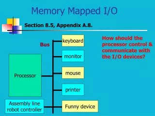
keyboard. monitor. Processor. mouse. printer. Assembly line robot controller. Funny device. Memory Mapped I/O. Section 8.5, Appendix A.8. How should the processor control & communicate with the I/O devices?. Bus. I/O Processor Control Interface.

Memory Mapped I/O
E N D
Presentation Transcript
keyboard monitor Processor mouse printer Assembly line robot controller Funny device Memory Mapped I/O Section 8.5, Appendix A.8. How should the processor control & communicate with the I/O devices? Bus
I/O Processor Control Interface What kind of control/data need be transferred? Keyboard: processor keyboard: data ready? read-data? keyboard processor: data ready Printer: processor printer: data-sent print font, resolution? printer processor: printing done. error conditions – out of paper, toner
I/O Processor Control Interface contd. Assembly-line robot: processor robot: move (direction, amount) action: grab, tighten robot processor: error- obstacle, diagnostics Hard disk: processor disk: seek sector seek track read/write block disk processor: data-ready error conditions – bad block
I/O Processor Control Interface contd. Should we include instructions for these control tasks? Is there enough uniformity between I/O devices to agree on a single set of instructions to communicate with them? How about the I/O devices we have not even foreseen yet? Hard to develop an instructionset to controltoday’s and tomorrow’s devices!
Control Data Memory-Mapped I/O Contd. Make the interface between the I/O device & processor soft. Let it be developed as a data structure. An I/O handler, a program that uses these data structures to coordinate the control and data transfer. Where does this control/data data structure reside?
0xffffffff I/O 0x7fffffff Stack Dynamic data Static data 0x10000000 Text/Program 0x400000 OS Memory-Mapped I/O Contd. The control and data registers are mapped in the memory. Memory-mapped I/O
0x81111114 Control register R Keyboard example getchar(): reads an ASCII byte from keyboard and deposits it in $v0. processor Keyboard $s0 0x7fffffff 0x7fffffff Data register poll: lw $t0, 4($s0) andi $t0, $t0, 0x1 beq $t0, $zero, poll getchar: move $v0, 0($s0) ?
0xf0000004 Control register R How Does Keyboard Know It’s Memory Map? #Bytes (256) Chip-Select 0 (CS0) CS Base(0xf0000000) processor Keyboard Chip Enable 0xf0000000 Data register
Producer Consumer Polling Polling some synchronization flag repeatedly until flag is true. Is it efficient to poll? Shared resource Lock Sometimes yes, sometimes no!
Device Data Rate Polling Overhead 1600X1200 pixels/fr 7.68 Mpixels/Fr 2B/Pixel 15.36 MB/Fr 60 Fr/s 921.6 MB/s Interlaced 30Fr/s: 460.8 MB/s
Polling overhead contd. Polling overhead: 600 cycles transfer to polling procedure, access the device, return to the user program. CPU: 1GHz Fraction of CPU time spent polling?: mouse: must be polled at least 30 times/s Polling clock cycles: 30 polls/s * 600 c/poll = 18000 c/s CPU clock cycles/s: 109c/s Polling overhead: (18000)/(109)=18*10-4% = .0018%
Polling overhead contd. Fraction of CPU time spent polling?: floppy disk: transfers in 2B units at a data rate of 100 KB/s. Polling rate?: (100 KB/s)/(2B/poll) = 50K polls/s Polling clock cycles: 50K polls/s * 600 c/poll = 30M c/s CPU clock cycles/s: 109c/s Polling overhead: (3*107)/(109)=.03 = 3%
Polling overhead contd. Fraction of CPU time spent polling?: network card: transfers in 8B units at a data rate of 10 MB/s. Polling rate?: (10 MB/s)/(8B/poll) = 1.25M polls/s Polling clock cycles: 1.25M polls/s * 600 c/poll = 750M c/s CPU clock cycles/s: 109c/s Polling overhead: (75*107)/(109)=.75 = 75%
Polling overhead contd. Fraction of CPU time spent polling?: video monitor: transfers in 16B units at a data rate of 320 MB/s. Polling rate?: (320 MB/s)/(16B/poll) = 20M polls/s Polling clock cycles: 20M polls/s * 600 c/poll = 12G c/s CPU clock cycles/s: 109c/s Polling overhead: (12*109)/(109)=12 = 1200%
Alternative to Polling Producer wakes up the consumer! Interrupts / Exceptions: term used in computer architecture. Exceptions/interrupts can be external or internal. Keyboard interrupts the processor to indicate that the data is ready. External --- interrupts. Internal exceptions: divide by zero, arithmetic overflow, data alignment error. Internal --- exceptions.
Polling is what we have seen: main () { while(1) { PollKeyboard(); } How to poll keyboard: Read port to see if a key is pressed Must poll every n ms, the minimal time period a key is pressed; otherwise user keystroke is lost. If the program has tasks to do: main () { task1(); PollKeyboard(); task2(); PollKeyboard(); … } Overhead: Overhead = Polling frequency × Polling overhead Ease of programming: Hard to mix polling with a normal process Why Interrupt I/O?
char input_buffer[1024]; main() { set_interrupt_handler(); task1(); task2(); /* process buffered input */ read_user_input(); // more tasks } void interrupt_handler(int type) { PollKeyboard(); … /* write to input_buffer */ } Details are platform-dependent Desktop systems: OS manages all interrupts, put input into buffers; or send signal to application programs Embedded systems: applications handle interrupts Interrupt-Based C Programming
Normal Control Flow In a processor, the program counter (PC) takes a sequence of values a0, a1, …, an-2, an-1 where each ak is the address of an instruction Ik. • Control transfer: each transition from ak to ak+1 • Flow of control, or control flow: sequence of control transfers “Smooth” control flow: Ik and Ik+1 are adjacent in memory Changes to smooth flow: Ik+1 not adjacent to Ik • Branches • Calls, returns
Exceptional Control Flow Exceptional control flow (ECF) Abrupt changes in control flow not caused by program statements and variables: Ik+1 is external to the program • Hardware timer goes off at regular intervals • I/O request completes, e.g., A/D conversion, disk I/O • Packets arrive at network adapter • Instruction attempts divide by zero • Arithmetic overflow occurs • Virtual memory page fault occurs • Memory access violation Occurs at all levels in a computer system: hardware, operating system, user
Exceptions • form of ECF • implementation details vary from system to system • DEFINITION: an abrupt change in the control flow in response to some change in the processor’s state • Event: change in processor’s state, where state is encoded in various bits and signals inside the processor • Event might be related or unrelated to current instruction
Classes of Exceptions Four classes of exceptions: • Interrupts • Traps • Faults • Aborts
Exception processing • How is an exception signaled? • How is the desired exception service indicated? • How does the processor prioritize and accept exceptions? • How is the control transferred from the interrupted program to the exception service? • How is the interrupted program resumed?
Exception processing: Exception signaling Internal exception: who initiates the exception? who needs to know that an exception has occurred? Processor controller needs to be aware of an exception. Exceptions are generated by instructions: Arithmetic overflow Illegal instruction Data alignment error
Processor IRQ: interrupt request Exception processing: Exception signaling Contd. External interrupt: Interrupts generated by external devices such as keyboard & mouse?
Exception processing: Exception signaling Contd. Priority encoder Level 1 Level 2 Processor I0 Level 3 I1 Level 4 I2 Level 5 Level 6 000: no interrupt 010: level 2 int. Level 7
Two General Mechanisms: • Centralized dispatch: exception handler decodes • the cause. (MIPS style) • (2) Vectored dispatch: the hardware based on • a vector number invokes the appropriate service. • (PowerPC style) Exception processing: Exception Service How can an exception service be specified? What is an exception service? A robot? A mechanical service? A procedure (program): its address specifies the desired service. Typically called ISP (interrupt service procedure).
PC: 0x80000080 add $t0, $t1, $t1 div $t0, $t3 mfhi $t2 addi $t2, $t2, 1 Exception handler 0x80000080 Exception processing: Exception Service Contd. PC:0x80000180
Cause Register Cause code 00 Exception Handler if (cause == Arithmetic Overflow) ArithmeticOverflowHandler(); else if (cause == DivideByZero) DivideByZeroHandler(); else if (cause == Illegal Instruction) IllegalInstructionHandler(); else if (cause == external interrupt) InterruptHandler(); ----- -----
Cause Register 4 Pending interrupts IP5 IP4 IP3 IP2 IP1 IP0 SW1 SW0 00 Cause code 00 Cause Register Part of conceptual co-processor 0 mfc0 $t0, $13 or mfc0 $t0, $cause
ISP address 4 byte Vector# 1 2 3 4 5 6 C System reset Data addr error Inst addr error Ext. interrupt Alignment error System call Vectored Interrupts:Motorola Each exception & interrupt has a 8-bit vector #: 0-255 (for Motorola 68xxx family) Starting address of ISP = vector#*4 + starting address of vector table = 0x1000 + 3*4 (for data addr error).
Addr: 0x00000000 Vector 0 Vector 1 Addr: 0x00000100 Vector 2 Addr: 0x00000200 Vector 31 Addr: 0x00001f00 Vectored Interrupts:PPC PPC maintains an exception vector table. Only 32 vectors available. Each vector is given 100 words of space in exception vector table. A primitive ISP goes in that space.
Exception processing: prioritization If multiple exceptions/interrupts raised simultaneously, how do we prioritize them? In general: internal exceptions (software raised) are always given higher priority than the external interrupts (hardware device initiated). Within software exceptions, there might be multiple levels of prioritization: 2 in MIPS. Within external interrupts, multiple levels of priority: 6 in MIPS.
Cause Register 4 Pending interrupts IP5 IP4 IP3 IP2 IP1 IP0 SW1 SW0 00 Cause code 00 Exception processing: prioritizationcontd. Look at all the pending interrupts at the entry into the exception-handler. If more than one is 1, choose based on the priority. Can a higher priority interrupt pre-empt the ISP for a lower priority interrupt? There can be nested exception service procedures!
Exception processing: Control transfer • Exception-handler is just like any other procedure. • Calling is not done through a procedure call. • It is called by the processor controller by forcing • its address 0x80000080 into PC. What should be saved before forcing 0x80000080 into PC (so that we can resume the interrupted program)? Current program’s state including its address.
K/U I.E. 8 15 Interrupt mask Exception processing: Control transfer Contd. Right before PC 0x80000080, the current PC is saved in EPC: PC EPC (Exception PC). EPC is Reg. 14 in co-processor 0: mfc0 $t0, $14 or mfc0 $t0, $EPC Other program state is kept in Status Register:
Exception processing: Control transfer Contd. While in exception-handler, can another exception be accepted? EPC gets overwritten similar to $ra! One of the first acts in exception-handler should be to save EPC, cause, and status register on a stack. While saving these registers, should we disable all the interrupts?
At entry into exception-handler: 0 0 old prev. current K/U K/U K/U K/U K/U K/U K/U I.E. I.E. I.E. I.E. I.E. I.E. I.E. 0 0 Exception processing: Control transfer Contd. • All exceptions are disabled. • K/U=0: kernel mode (supervisor mode).
Exception processing: Control transfer Contd. exception-handler: mfc0 $k0, $cause mfc0 $k1, $EPC sw $k0, -4($sp) sw $k1, -8($sp) sw $t0, -12($sp) addi $sp, $sp, -12 mfc0 $t0, $status ori $t0, $t0, 0x1 mtc0 $status, $t0 andi $k0, $k0, 0x3c beq $k0, $zero, interrupt --- --- exception-handler() { /* keep the interrupts disabled */ (1) save EPC, cause, status regs on system stack. (2) enable interrupts. (3) decode cause and call appropriate ISP. }
RI=1: recoverable Machine State Register (MSR) 0 EE PR 0 IP IR DR 0 0 RI LE IP=0: exception Vector table Starts at 0x000 else 0xfff PR=0: supervisor =1: user EE=ext. interrupt enable =0: disable =1:enable LE=0 Big-endian Exception processing: Control transfer PPC
Machine Status Save/Restore Register 0 (SRR0) PC saved here Machine Status Save/Restore Register 1 (SRR1) Exception specific info Save MSR bits 0000 000000 1-4 10-15 E E P R I P R I L E MSR PPC Exception Registers
On an exception: IL E E E P R I P R I L E 0 0 0 MSR PPC Exception Registers mtspr SRR0, r2: r2 SRR0 mfspr r3, SRR1: SRR1 r3 mtmsr r2: r2 MSR mfmsr r3: MSR r3 Each exception handler must save SRR0, SRR1, and MSR before enabling exceptions (EE=1).
PPC Exception Priorities Non-maskable, asynchronous: Priority 1: System reset Priority 2: Machine check Synchronous, maskable: instruction dependent ones such as alignment, FP: Priority 3, 4. Asynchronous, maskable: external interrupt (priority 5) decrementer (priority 6).
K/U K/U K/U I.E. I.E. I.E. Exception processing: resume Need to return from the exception handler to the interrupted program. Should we just use jr EPC? A special instruction: rfe return from exception. only restores the status register. EPC PC: need to use jr explicitly.
Exception processing: PPC resume return from interrupt: rfi . MSR[16-23, 25-27, 30-31] SRR1[16-23, 25-27, 30-31] PC SRR0[0-29]||00
IRQ processor Keyboard 0x7fffffff Data register 0x81111114 Control register R Interrupt Driven Keyboard ISP: getchar: lw $v0, 0($s0) jr $ra
IP5 IP4 IP3 IP2 IP1 IP0 SW1 SW0 00 Cause code 00 Interrupt-Handler exception-handler() { if (cause == interrupt at level 1) getchar(); } andi $t0, $k0, 0x800 beq $t0, $zero, otherinterrupt jal getchar otherinterrupt: -- --- --- noninterrupt: -- --- --- rfe jr $k1 exception-handler: mfc0 $k0, $cause mfc0 $k1, $EPC sw $k0, -4($sp) sw $k1, -8($sp) sw $t0, -12($sp) addi $sp, $sp, -12 mfc0 $t0, $status ori $t0, $t0, 0x1 mtc0 $status, $t0 andi $t0, $k0, 0x3c bne $t0, $zero, noninterrupt
IP5 IP4 IP3 IP2 IP1 IP0 SW1 SW0 00 Cause code 00 .ktext 0x80000080 sw $a0, save0 sw $a1, save1 mfc0 $k0, $13 #cause mfc0 $k1, $14 #EPC sgt $v0, $k0, 0x44 bgtz $v0, done move $a0, $k0 move $a1, $k1 jal print_excp done: lw $a0, save0 lw $a1, save1 addiu $k1, $k1, 4 rfe jr $k1 .kdata save0: .word 0 save1: .word 0 Interrupt-Handler A-35, HP 0000
IRQ processor Keyboard 0x7fffffff Rec. Data register 0x81111114 Rec. Control reg IE R Trans. Data Reg. 0x81111118 Trans. Control Reg. IE R 0x8111111c Transmitter Control The character typed at the keyboard is echoed back to the keyboard (and displayed). lw $t0, 0($s0) ori $t0, $t0, 0x2 sw $t0, 0($s0) #enables interrupt
BD IP5 IP4 IP3 IP2 IP1 IP0 SW1 SW0 00 Cause code 00 Status Register K/U 00 Interrupt mask Exception level EXL I.E. 8 15 MIPS-32 Exception handling Cause register BD=1: an instruction in the branch delay slot caused this exception.
.ktext 0x80000180 sw $a0, save0 sw $a1, save1 mfc0 $k0, $13 #cause srl $a0, $k0, 2 andi $a0, $a0, 0xf bgtz $a0, done move $a0, $k0 mfc0 $a1, $14 jal print_excp done: mtc0 $0, $13 mfc0 $k0, $12 andi $k0, 0xfffd ori $k0, 0x1 mtc0 $k0, $12 lw $a0, save0 lw $a1, save1 addiu $k1, $k1, 4 eret .kdata save0: .word 0 save1: .word 0 MIPS-32 Interrupt-Handler