Low-cost 802.11 Wireless Infrastructure Networks
150 likes | 255 Vues
Low-cost 802.11 Wireless Infrastructure Networks. Stefan Savage and John Bellardo Department of Computer Science and Engineering University of California, San Diego. Motivation. Large-scale 802.11 deployments are expensive

Low-cost 802.11 Wireless Infrastructure Networks
E N D
Presentation Transcript
Low-cost 802.11 Wireless Infrastructure Networks Stefan Savage and John Bellardo Department of Computer Science and Engineering University of California, San Diego
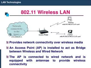
Motivation • Large-scale 802.11 deployments are expensive • Capital expenditures typically < 35% (and hardware is on commodity price curve) • Operational expenditures • Site-survey • Test and tuning • Network wiring and provisioning • Ongoing management (software update, rebalance, etc) • Our goal: make it cheap and trivial to provide building or campus-wide 802.11 APs (OpEx -> 0)
Assumptions • Radio hardware is cheap • Multiple independent radios in a package is reasonable • Antenna technology is not • Omni antennas (low gain/directional separation) • Intra/Internet access usage model • Not point to point • Largely homogenous administrative domain • Not dealing with apartment building problem (initially) • Indoor focus • 3D, dense deployment, complex RF domain, significant spatial and temporal load shifts • Must not require 802.11 client modifications • Ok as optimization
Aside: Why use 802.11? • Bad experience with simulation • Our wireless immigration project (USENIX Sec ’03) • Send CTS with large duration to freeze channel (devestating in simulation, then we built it) • Have tried three wireless simulators (including $$$) – can’t find any that predict our measurements • Multi-path, fading, variable noise, people (i.e. moving bags of water) • Variable xmit pwr, receive sensitivity, power spectrum, MAC behavior on client NICs • We want experience with real traffic driven by real users, hence we need to build real systems • Not equipped/funded to build a lot of radios • Although we do have some (CalRadio – at end of talk)
Two elements of our work • Radio Tomography and Frequency Management(RTFM) • Measurement-based inference of RF domain capacity and contention • Auto AP configuration to maximize system goodput • Frequency, transmit power, CCA, coding • Goal: no site survey, no tuning, no manual configuration • LessWire • Simplified multi-hop routing (3 hop max) • Best-exit routing wrt RF domain impact • Goal: opportunistic use of wiring, expand coverage/density
Radio Tomography • Key questions • If I send pkt x at rate r with power t on channel z, what is the distribution of delivery delay times? • Why? • Background interference • Co-channel interference • Client<->AP propagation (fading, multipath, etc)
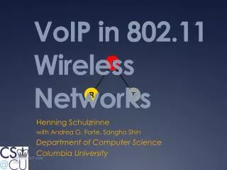
•AP• •AP• •AP• Radio Tomography: first try • Naïve approach • Model nodes as point transmitters with set xmit range r and channel z • If two sphere’s overlap, delay is proportional to the sum over load • Re-color, re-size to minimize delay • Why this doesn’t even vaguely work • Non-uniform propagation • Channel not exclusive • Coding matters • Channel conditions and clients change
Radio Tomography: 2nd & 3rd attempts • Next idea: • Observe visible MACs and share among APs • If two nodes share the same node then assumethey interfere • Problems: • Incredibly conservative (ignores attenuation and RF capture) • Next idea: • Measure RSSI and infer impact on xput • Fine grained “ground-truth” measurements(sample over every 3x3 feet by hand) • Problems • RSSI is very very noisy and highly variable • Hard to infer “ground truth” from few samples • Very poor predictor of pkt delivery • Happy to learn about any non-brittle modelshere that work
Radio Tomography: current approach • Synchronized Co-Channel Interference Inference • Idea: create interference and see impact (analogies to slow start) • APs send short burst on channel x at time t and rate r • Other APs measure change in re-transmission probability and back-to-back xmit timing at same time (CCA indication) • Infer same from client based on retry bit in header & CRC failures • Findings • Rate sensitivity • Both for data (makes sense)and interferer (unsure) • Discontinuities (fastest rates -> practically slower) • Strong bimodality • Good at characterizing interference • ~85% for sub-second samples • Gotchas: low S/N
RF Management • RF Parameter optimization (work in progress) • Minimize xmit power to maximally split offered load across APs • Color frequency and set CCA to minimize interference effects • Research questions • NP-hard, Heuristic challenge – ordering of power/frequency opt • How often to re-optimize? • Don’t want to react to short workload dynamics (ftp transfer) or RF dynamics (jiffy pop time-scale) • Client delay on reassociation • Some NICs very bad • Our APs support fast handoff (SyncScan, UCSD-TR) but requires client mods to take advantage • Want to react quickly to AP failure • Centralized vs distributed control? • Impact if some nodes don’t play?(e.g. static frequency inholding)
LessWire • Idea: use additional radios to provide multi-hop backhaul • Research challenges • Point-to-multipoint route optimization over RF domain (not ad hoc routing) • Interaction with RF management • Backhaul-only channels vs joint assignment • Optimize freq/power assignment over “opportunity cost” of a route • Simplicities from being short hop (2-3 hops max) network (very low state)
Where we are • RTFM prototype limping along at UCSD • Interference inference • Background channel quality • Co-channel impact on predicted delay on given frequency • Extrapolate rate impact based on empirical curves • Greedy channel assignment based on static threshold • Lots of work left… (CCA validation, TX power, better assignment, more features to classifier) • LessWire • In algorithmic stage – no results to report today • We are assuming that wired bandwidth is infinite
UCSD CSE Infrastructure • 266Mhz Soekris w/40GB trace store • Dual-radio Atheros 5212 miniPCIs • Driver hacks for CCA adjust, per-packet TPC&rate control • Global time synced packet scheduling • 5Ghz deployment on two floors-12APs(soon 2 more + indoor/outdoor-40APs)
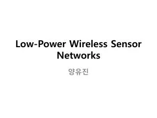
Keys 8-LEDs 8-GPO Flash SRAM RF PORT 16b-Latch 512K x 16 256Kx16 Decode Optional SPKR MIC Logic PEEL +3.3, +2.8, +1.8 Power Supplies RF serial bus Amplifier SPI, Keys, GPIO I2S External McBSP2 McBSP0 McBSP1 Stereo Memory CODEC Interface TLV320AIC23 5409 ALU SPI 11.2896MHz DSP DMA Peripherals I2S (100MIPS) Program SRAM JTAG ROM Test 32K x 16 16K x 16 TMS320VC5409 UCSD Infrastructure: CalRadio I • Joint project of UCSD CalIT2, ECE and CSE • Intersil baseband, 2.4Ghz RF, DSP-based MAC (TI ‘C5471/ARM7, Symbol derived IP, about 4”x4”) • Designed to allow L2 experimentation/innovation
LVDS Serial Interfaces UCSD Infrastructure: CalRadio II • More aggressive: physical layer innovation • Several RF modules being constructed (2.4, 5Ghz WiFi, 2x2 MIMO 900Mhz, 3-10Ghz UWB) • Modulation all in FPGA, Matlab/Simulink compatible