MICE
270 likes | 425 Vues
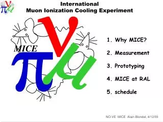
n. m. p. MICE. The International M uon I onization C ooling E xperiment. MICE Overview 1. Why, what and how? 2. requirements on the beam line 3. other desirable features of the beam line 3. Conclusions. Major challenges tackled by R&D expts.

MICE
E N D
Presentation Transcript
n m p MICE The International Muon Ionization Cooling Experiment
MICE Overview 1. Why, what and how? 2. requirements on the beam line 3. other desirable features of the beam line 3. Conclusions
Major challenges tackled by R&D expts High-power target . 4MW . good transmission MERIT experiment (CERN) Fast muon cooling MICE experiment (RAL) , MUCOOL Fast, large aperture accelerator (FFAG) EMMA (Daresbury) ISS baseline
IONIZATION COOLING reality (simplified) principle: ….maybe… this will surely work..! Cooling is necessary for Neutrino Factory and crucial for Muon Collider. Delicate technology and integration problem Need to build a realistic prototype and verify that it works (i.e. cools a beam) Can it be built? Operate reliably? What performance can one get? Difficulty:affordable prototype of cooling section only cools beam by 10%, while standard emittance measurements barely achieve this precision. Solution: measure the beam particle-by-particle state-of-the-art particle physics instrumentation will test state-of-the-art accelerator technology.
10% cooling of 200 MeV/c muons requires ~ 20 MV of RF single particle measurements => measurement precision can be as good as D ( e out/e in ) = 10-3 never done before Coupling Coils 1&2 Spectrometer solenoid 1 Matching coils 1&2 Matching coils 1&2 Spectrometer solenoid 2 Focus coils 1 Focus coils 2 Focus coils 3 m Beam PID TOF 0 Cherenkov TOF 1 RF cavities 1 RF cavities 2 Downstream TOF 2 particle ID: KL and SW Calorimeter VariableDiffuser Liquid Hydrogen absorbers 1,2,3 Incoming muon beam Trackers 1 & 2 measurement of emittance in and out
Coupling coils and 200 MHz RF Cavities More professionally engineered view: Focus coils and LH2 Absorbers ToF2, Calorimeter ToF1, diffuser Solenoids, Matching coils and Scintillating fiber Tracker CKOV ToF0
THE MICE COLLABORATION -128 collaborators- • Universite Catholique de Louvain,Belgium • University of Sofia,Bulgaria • The Harbin Institute for Super Conducting Technologies PR China • INFN Milano, INFN Napoli,INFN Pavia, INFN Roma III,INFN Trieste,Italy • KEK, Kyoto University, Osaka University,Japan • NIKHEF, The Netherlands • CERN • Geneva University, Paul Scherrer InstitutSwitzerland • Brunel,Cockcroft/Lancaster, Glasgow, Liverpool, ICL London, Oxford, Darsbury, RAL, SheffieldUK • Argonne National Laboratory, Brookhaven National Laboratory, Fairfield University, University of Chicago, Enrico Fermi Institute, Fermilab, Illinois Institute of Technology, • Jefferson Lab, Lawrence Berkeley National Laboratory, UCLA, Northern Illinois University, University of Iowa, University of Mississippi, UC Riverside, University of Illinois at Urbana-ChampaignUSA
MICE FIRST BEAM IN FEBRUARY 2008 Final PID: TOF Calorimeter Demonstrate feasibility and performance of a section of cooling channel by 2010 4T spectrometer II Status: Approved at RAL(UK) First beam: 10-2007 Funded in: UK,CH,It,JP,NL,US Further requests: JP,UK,US,It... Cooling cell (~10%) b=5-45cm, liquid H2, RF 4T spectrometer I TOF Single-m beam ~200 MeV/c Liquid-hydrogen absorbers Prototyping: 200MHz RF cavity with beryllium windows Scintillating-fiber tracker
MICE STEPS and PHASES PHASE I m Febuary 2008 STEP I STEP II April 2008 PHASE II STEP III July 2008 STEP IV Delivery of 1st FC ~May 2009 STEP V >summer 2009 STEP VI 2010
MICE Status Funding Funding for Phase I is secured some pending issues with INFN, support for visitors at RAL, beamline electricity Funding for Phase II is essentially secure (excellent news from US, China summer07) BUT: UK Phase II still awaiting decision, Japan for absorbers, SW calorimeter Construction DAQ, CKOV1 arrived at RAL in July 2007 Tracker I arrived at RAL Nov14 2007 Combined Cosmic Test in November-December Beam line construction in full swing; will be closed and safe by Jan20 2008 TOF0/1, KL: detectors built, mechanics finishing, ETA at RAL 15 Dec 2007 Spectrometer solenoid I to arrive FNAL jan 2008 and RAL March 2008 Tracker II to arrive RAL in Feb 2008 Spectrometer solenoid II to arrive RAL in May 2008 TOFII June 2008 SW later in 2008 step IV to be defined by AFC module I. Tender issued. OK from UK-STFC pending global review result end of 2007. Crucial issue for PhaseII is RF tests in magnetic field: RF cavity I arrived in 2006, tested to 19MV/m coupling coil I will arrive FNAL end 2008.
Challenges of MICE: • (these things have never been done before) • Operate RF cavities of relatively low frequency (201 MHz) at high gradient (nominal 8MV/m in MICE, 16 MV/m with 8 MW and LN2 cooled RF cavities) • in highly inhomogeneous magnetic fields (1-3 T) • dark currents (can heat up LH2), breakdowns • 2. Hydrogen safety (substantial amounts of LH2 in vicinity of RF cavities) • 3. Emittance measurement to relative precision of 10-3 in environment of RF bkg • requires • low mass (low multiple scattering) and precise tracker • fast and redundant to fight dark-current-induced background • precision Time-of-Flight for particle phase determination (±3.60 = 50 ps) • complete set of PID detectors to eliminate beam pions and decay electrons • and… • 4. Obtaining (substantial) funding for R&D towards a facility that is not (yet) in the plans of a major lab
The experiment MICE wants to do Beam optics and diffuser to provide this set of emittances Changeover should be fast (30') and should not require switching off MICE magnets. MICE diffuser system: equilibrium emittance = 2.5 mm.radian curves for 23 MV, 3 full absorbers, particles on crest repeat this curve for various momenta, absorbers, etc..
Requirements on detectors for MICE: • Must be sure to work on muons • 1.a use a pion/muon decay channel with 5T, 5m long decay solenoid • 1.b reject incoming pions and electrons • TOF over 8m with 70 ps resolution+ threshold Cherenkov • 1.c reject decays in flight of muons • downstream PID (TOF2 + calorimeters) • 2. Measure all 6 parameters of the muons x,y,t, x’, y’, z=E/Pz • tracker in magnetic field, TOF • 3. Resolution on above quantities must be better than 10% of rms of beam • at equilibrium emittance to ensure correction is less than 1%. • + resolution must be measured • 4. Detectors must be robust against RF radiation and field emission Design of MICE detectors and beam test results satisfy the above requirements
MICE is a precision experiment! Cooling in MICE is only ~10% (eout/ ein)exp = 0.9 establishing effect requires % precision, optimizing it requires permil precision This is the goal of MICE. requires: statistics of 106 muons per measurement point (a few hours at 100 good muons/s) systematics at permil level, individual sources must be a small fraction of this! Beam related systematics In principle, individual muons can be reweigted to form an 'ideal beam' This is not very easy – avoid reweighting factors of more than ~50% overall Alignment in x,x', y,y', p has been studied and leads to the constraint that beam offsets should not exceed 3-5% of beam sizes at diffuser Effect of mismatch, x-y asymmetries, coupling, dispersion have not been completely studied
Experimental Systematics Mice-fiction in 2009 or so. . MICE measures e.g. (eout/ ein)exp = 0.904 ± 0.001 (statistical) and compares with (eout/ ein)theory. = 0.895 and tries to understand the difference. SIMULATION experimental systematics: modeling of spectrometers or beam is not as reality theory systematics: modeling of cooling cell is not as reality REALITY MEASUREMENT
Requirements on MICE beam -- 'single' muons of either sign (low intensity, long spill, dt >~ 100 ns) -- beam momentum: 140MeV/c – 240 MeV/c (MICE channel momentum range) + higher momentum desirable: 240 + 1sp = 265 MeV/c to cover phase space incl. amplitude-momentum correlation. -- emittance: optically matched, 1-10 mm.rad, symmetric in x-y, sp /p ~ 10% from: below equilibrium emittance (2.5 mm.rad) <== this is not easy to: exceed acceptance of MICE (10 mm rad) -- time structure: pulse duration*rep rate = RF duty factor of 0.001 this is achieved with rep. rate 1Hz and pulse length of 1ms (ISIS) -- statistics: ~ 100 good muons per second (i.e. within 15cm radius in tracker) this requires 600 good muons per pulse (to allow RF timing cut of 1/6) Fewer muons --> run the facility longer, cost more! -- alignment: requires offset < 3% of beam size at MICE (small reweight) i.e. ~1mm centering in x,y ~3mrad in x' y' at absorber -- purity: electrons and protons are easy to discriminate (if not too numerous) pion/muon contamination should be less than 1/10 (1/100 desirable)
Target and time structure Target mechanism has been developed to dip Ti target into ISIS beam in the last ms of ISIS cycle 80 g acceleration achieved ! 1 Hz rate Tested with >3M actuations Wear solved with Diamond bearings Will be installed in Xmas 07 shut down micro structure: 100ns 330ns detectors and DAQ well adapted to this structure
Upstream beam line: Xmas work VERY TIGHT working hard
Beam line -- Construction at RAL is in full swing main issues: -- target just in time.. now authorized! to be installed over X-mas -- repairing the PSI solenoid and cold check -- original misalignment of assumed point of target impact on beam by 2cm... being fixed -- Q4-6 refurbishment finished; Q7-9 still ongoing tight schedule -- schedule of Xmas shut down is very tight! -- beam monitors and TOF0 are all somewhat late risk: delays in startup At this point the beam line does not include: -- collimators (maybe needed for small emittance beam) -- alignment correctors there is a couple schemes possible, but not completely worked out correcting dipoles or trim coils on quadrupoles risk: loss of performance and practicality -- ratio of particle production to beam loss monitors not completely understood risk: considerable loss of performance.
Aspirational MICE Schedule as of October 2007 m Febuary 2008 STEP I STEP II April 2008 STEP III July 2008 STEP IV Delivery of 1st FC ~May 2009 STEP V >summer 2009 STEP VI end 2009 (or 2010)
Goals: I – Commission target Establish beam rates Find match and alignment II - Determine whether we have all knobs necessary to draw emittance vs. transmission curve. Measure emittance Run plan -- steps I and II m STEP I Jan-Feb 2008 STEP II march –April 2008 Runnng time: Take 200-400 muons per 1ms spill once per second In steps I-IV 1% (0.1%) emittance meast will take ~1 (100) minute 6 times longer in steps V and VI where phase matters. preliminary estimate STEP I requires 60 shifts (20 days of running) beam line commissionning, target tuning (rates), DAQ and detector shake down STEP II requires 150 shifts (50 days, will extend in summer 2008) Alignment of beam x,x’,y,y’, (Lack of) dispersion, check range of transverse emittance, and range of momenta measure emittance and… publish first paper total for steps I & II: 70 days
Conclusions 0. MICE will be taking data in 75 days 1. The collaboration is making excellent progress in all fronts: Simulations, R&D, engineering, prototyping and construction Funding for phase I is complete, Funding for PhaseII is in good shape to assure that step VI can be performed in good time for 2010. 2. MICE will start phase I data taking in february 2008 Steps I, II, III will allow beam commissioning, tuning, first measurement of emittance and verification of systematics 3. The MICE beam line has been designed to provide adequate statistics and the range of momentum and emittances needed to measure transmission, cooling and equilibrium emittance with high precision. 4. To the reviewers: you will do MICE a great help by finding the bug before we find it the hard way in 2008. THANKS!