CALIFES linac
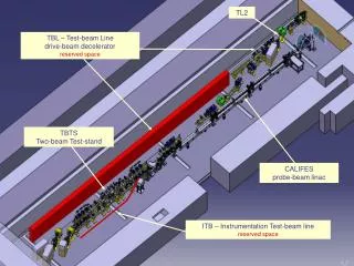
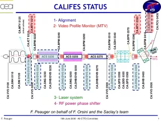
Cavity BPM for CALIFES C. Simon, M. Luong, D. Bogard, W. Farabolini, J. Novo CTF3 Meeting – 27-29 January 2009. CALIFES linac. ITL. DUM 0450. ACS 0230. ACS 0250. ACS 0270. TBTS. CA.FCU 0430. CA.MTV 0420. CA.MTV 0215. CA.MTV 0125 (virtual cathode). CA.MTV 0390. CA.BPR 0370.

CALIFES linac
E N D
Presentation Transcript
CavityBPM for CALIFESC. Simon, M. Luong, D. Bogard, W. Farabolini,J. Novo CTF3 Meeting – 27-29 January 2009
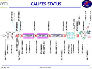
CALIFES linac ITL DUM 0450 ACS 0230 ACS 0250 ACS 0270 TBTS CA.FCU 0430 CA.MTV 0420 CA.MTV 0215 CA.MTV 0125 (virtual cathode) CA.MTV 0390 CA.BPR 0370 CA.ICT 0210 CA.BPM 0410 CA.SDH 0340 CA.BPM 0240 CA.BPM 0310 CA.BPM 0220 CA.BPM 0260 CA.BPM 0380 CA.DHG/DVG 0130 CA.DHB/DVB 0250 CA.DHG/DVG 0245 CA.DHG/DVG 0225 CA.DHG/DVG 0385 CA.DHB/DVB 0230 CA.DHG/DVG 0320 CA.DHB/DVB 0270 CA.DHG/DVG 0265 CA.QFD 0350 CA.BHB 0400 CA.SNG 0230 CA.QFD 0360 CA.SNG 0250 CA.QDD 0355 CA.SNH 0110 CA.SNI 0120 CA.VVS 0300 CA.VVS 0200 CA.VVS 0100 CA.VVS 0500 6 BPMs are installed on the CALIFES linac
Reentrant Cavity BPM for CALIFES • It is operated in single and multi-bunches modes • The cavity is fabricated with titanium and is as compact as possible : • ~125 mmlength and 18 mm aperture • 4 mmgap Reentrant Part Bent coaxial cylinder designed to have: - a large frequency separation between monopole and dipole modes - a low loop exposure to the electric fields
RF characteristics • RF characteristics of the cavity: frequency, coupling and R/Q Monopole and dipole transmission measured by the network analyzer Monopole and dipole reflection measured by the network analyzer • Similar results from one BPM to another, and in-situ results are comparable to Saclay • in-lab measurements BPM Due to tolerances in machining, welding and mounting, some small distortions of the cavity symmetry are generated. This asymmetry is called cross talk and the isolation is evaluated > 26 dB.
Signal Processing • Hybrids installed close to BPMs in the CLEX • Multiport switches used to have one signal processing electronics to control six BPMs. • Analog electronics with several steps to reject the monopole mode Hybrid couplers • RF electronics used synchronous detection with an I/Q demodulator.
Control Command of BPMs 1/Sampling with acqiris boards and readout signals on OASIS 3/Results sent on graphic windows under JAVA and in a file to be used with Matlab 6 BPMs implemented Beam position 2/Signal processing: Digital Down Conversion - raw waveform multiplied by a local oscillator of the same frequency to yield a zero intermediate frequency - real and imaginary parts of each IF are then multiplied by a 60 coefficient, symmetric, finite impulse response (FIR), low pass filter with 40MHz 3dB bandwidth
Sd(n) ~ 30 ns Simulations (1) • Signal voltage determined by the beam’s energy loss to the dipole mode. Dipole mode signaldepends on frequency fi and external coupling Qi of this mode single bunch Φ(t) = heaviside function, q = bunch charge, R0 = 50 Ω, (R/Q)i = coupling to the beam and ζi = 2 (dipole mode) 32 bunches Dipole mode signal in single bunch mode Dipole mode signal in 32 bunches mode Signal in 32 bunches mode behind RF electronics Signal in single bunch mode behind RF electronics ~10 ns
Simulations (2) • Noise is determined by : Thermal Noise : kb = Boltzmann constant, BW (Hz) = Bandwidth, T (K) = Room Temperature. • Noise from signal processing channel: • with Pth = Thermal noise, NF=Total noise figure of the signal processing, Fi and Gi respectively the noise factor and the gain of component i. • Re-entrant Cavity at CALIFES • Environment Noise RMS: 66 µV (measured at FLASH) • Δsignal(gain adjusted to get an RF signal ~ 0 dBm, simulated in single bunch) • with 5 mm offset : 590 mV (simulated), Noise: 0.5 mV (calculated) Resolution : 3.2 µm (simulated) • with 0.1 mm offset : 555 mV (simulated), Noise: 0.1 mV (calculated) Resolution : 100 nm (simulated)
BPM calibration (1) CA.ICT 0210 CA.BPM 0220 • All BPMs have same electronics and same losses coefficients should be the same • Charge calibrated with charge calculated by ICT
Beam studies (1) • τ too long on S channel (green) problem with diode • Impedance problem? -> Move lowpass filter ICT • channels Amplitude of signals corresponds to 6 nC with 150 bunches determined thanks to ICT
Beam studies (2) Dy I and Q channels Signals minimized beam offset minimized S channels Charge ~ 6 nC read by the first and second BPM. ~ 100 % transmission behind 1st section
Beam studies (3) • Signal frequency: 100 MHz • Shape of Dy shows in the pulse train : • - charge not constant • or • beam position not constant S Channel Dy I and Q channels Simulation of I and Q signals
BPM calibration (2) CA.DHG/DVG 0320 CA.BPM 0380 R = transfer matrix from steerer to BPM • Magnets switched off between steerers and studied BPM to reduce errors and simplify calculation. • Move beam with one steerer in horizontal and vertical frame. • Average of 500 points for each steerer setting. • Calculate for each steerer setting, the relative beam position in using a transfer matrix between steerer and BPM : • Dx = R12*Dx’(angle at steerer)
Summary • Reentrant cavity BPM features for CALIFES: • Operated in single and multi-bunches • Single bunch resolution potential < 1 µm • Charge of beam measured • Software under development. • First beam seen by BPMs Dec. 2008 • New beam tests end of March 2009
Acknowledgements Thanks to CERN and CEA teams Thanks to Pascal Contrepois Aline Curtoni Stéphane Deghaye Mick Draper Patrick Girardot Francis Harrrault Pierre-Alain Leroy Fabienne Orsini Franck Peauger Anastasiya Radeva Lars Soby Thank you for your attention