Download
1 / 41
410 likes | 513 Vues
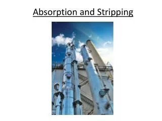
Learn about packed tower design, random packing, structured packing, mass balance equations, and graphical techniques for chemical absorption and stripping processes. Understand theoretical stages, operating lines, Kremser method, and hydraulics of packed towers. Get insights into pressure drop correlations and models for efficient gas-liquid separation.

E N D
Typical Absorber Effluent Air 70 ppm (molar) acetone Solvent (water) 1943 kgmol / hr Packed Tower Feed (air + acetone) 703 kgmol / hr 1.4 mol % acetone Water Out
Mass Balance Lo, Lm, xo, Xo G1, Gm, y1, Y1 Tray 1 Tray N LN, Lm, xN, XN GN+1, Gm, yN+1, YN+1
The “Theoretical” Stage LN-1, Lm, xN-1, XN-1 GN, Gm, yN, YN “Leaving” streams in thermodynamic equilibrium “Passing” streams linked by material balance Stage N LN, Lm, xN, XN GN+1, Gm, yN+1, YN+1
Absorber Operating Line Solvent 200 80/4 4 CO2 Tray 1 200/4 80/8 Molar Flows Tray 2 4 CO2 200/8 80/12 4 CO2 Tray 3 200/12 80/16 Tray 4 4 CO2 Solvent / CO2 200/16 80/20 N2 / CO2
Graphical Technique Figure 6.8 Continuous steady-state operation in a counter-current contactor with equilibrium stages (a-absorber, b–stripper) .
Graphical Technique Figure 6.9 Operating lines for an absorber
Kremser Method for Theoretical Trays (Absorber) G1,y1 Lo, xo Tray 1 Tray N LN, xN GN+1, yN+1
Kremser Method for Theoretical Trays (Stripper) G1,y1 Lo, xo Tray 1 Tray N LN, xN GN+1, yN+1
Example Carbon Disulfide, CS2, used as a solvent in a chemical plant, is evaporated from the product in a drier into an inert gas (essentially N2) in order to avoid an explosion hazard. The vapor-N2 mixture is to be scrubbed with an absorbent oil, which will be subsequently steam stripped to recover the CS2. The CS2-N2 mixture has a partial pressure of CS2 equal to 50 mm Hg at 24 C and is to be blown into the absorber at essentially standard atmospheric pressure at the rate of 50,000 ft3 / hr. The vapor content of the gas is to be reduced to 0.5 %. The absorption oil has a molecular weight of 180. The oil enters the absorber free of CS2. The oil – CS2 solution follows Raoult’s Law. The vapor pressure of CS2 at 24 C is 346 mm Hg. Determine: The minimum liquid / gas ratio For a liquid / gas ratio of 1.5 times the minimum, determine the flow rate of oil in lb / hr The required theoretical stages graphically and from the Kremser method.
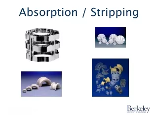
Packed Tower Design Random Packing
Structured Packing Fair, J.R., Seibert, A.F., Behrens, M., Saraber, P.P., and Olujic, Z. “Structured Packing Performance-Experimental Evaluation of Two Predictive Models ”,Ind. Eng. Chem. Res. 39 (6), 1788-1796 (2000).
Mass Balance Area = S Change in gas composition dZ = Flux out of gas
Design Equations Mass HTUOG NTUOG Unidirectional diffusion Eqn. 3-35
HTUOG Calculation Two resistance theory - need individual coefficients and area from mass transfer model: Onda, K., Takeuchi, H., Okumato, Y., “Mass Transfer Coefficients Between Gas and Liquid Phases in Packed Columns,” Journal of Chemical Engineering of Japan, 1, 56 (1968).
Onda Equations • c= 61 dyne /cm for ceramic packing • c= 75 dyne /cm for steel packing • c= 33 dyne /cm for plastic packing Units on ky and kx are length per time
NTUOG Calculation (Absorber Example) Vout = 62 lbmol/hr 3.2 mol % NH3 Lin = 488 lbmol/hr 35 NTUOG 30 95 % NH3 removal 25 20 15 10 Vin = 100 lbmol/hr 40 mol % NH3 5 0.0 0.10 0.20 0.30 0.40 y
NTUOG Calculation (log mean approximation) Assumes dilute solution and plug flow of each phase
Packed Absorber Example Solvent (water) 2.2 kmol / sec xo = 0 Effluent Air (y1 = 0.004) Data: yi = 40 xi kx = 0.0176 kmol /m2 sec ky = 0.0080 kmol / m2 sec aw = 100 m2 / m3 Packed Tower CSA = 1.5 m2 Find: NOG, HOG, Z Feed (air + SO2) 0.062 kmol / sec (yN+1 = 0.016) Water + SO2 Out
10 Minute Problem A packed absorption tower yields a concentration based. NTUOG of 10. Determine the tower height given the following information (The concentrations of the transferred component are dilute in both the liquid and gas). Data: Tower diameter = 5 ft. Gas density = 0.20 lb/ ft3 Gas superficial velocity = 3 ft / sec Kog = 0.01 m /sec m = 2.0 P = 1 atm, T = 80 F ae = 200 m2 /m3
Packed Tower Hydraulics(random packing) • Leva plot technique • Stichlmair model
Pressure Drop (Leva) Plot Figure 6.35 (a) Generalized pressure drop correlation for packed columns. (b) Correction for liquid density. (c) Correction for liquid viscosity.
Stichlmair Model Stichlmair, J., Bravo, J.L., Fair, J.R., “General Model for Prediction of Pressure Drop and Capacity of Countercurrent Gas/Liquid Packed Columns,” Gas Separations and Purification, 3:19-28 (1989)
Stichlmair Model (flood point) Infinite pressure drop at the flood point
Example A tower packed with 1 in. Ceramic Intalox saddles is to be built to treat 25,000 ft3/ hr of entering gas. The ammonia content of the entering gas is 2 percent by volume. Ammonia-free water is used as the absorbent. The temperature is 68 F and the pressure is 1 atm. The ratio of the gas flow to the liquid flow is 1 lb of gas per lb of liquid. The tower diameter is 1.67 ft. Using both the Leva plot and the Stichlmair correlation determine the total tower pressure drop if the tower packed height is 20 feet.
10 Minute Problem An air-water test is being run on a 10 foot bed of 1 inch (25 mm) metal Pall rings. The air rate is 350 ft3 / min and the liquid rate is 15 GPM / ft2. The tower is 16.8 inches in diameter, the operating pressure is 1 atm and the temperature is 80 F. What is the total column pressure drop?
Carbon Capture and Sequestration Power N2 H2O Boiler / Generator CO2 + N2 + H2O CO2 Recovery CO2 Trace Components Coal Air (O2 + N2) Underground Formation
Absorption with Chemical Reaction Flue Gas Out CO2 Stripper 100–120 °C Absorber 40–65 °C Heat X Flue Gas In 5 % O2 12 % CO2 83 % N2 Reboiler Rich Amine Lean Amine
Mass Transfer with Fast Reaction CO2 + 2MEA = MEACOO- + MEAH+
Mass Transfer with Fast Chemical Reaction (CO2 + MEA) MEA (monoethanolamine)