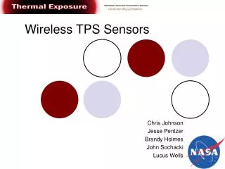
Wireless TPS Sensors
This document presents a detailed design review of wireless Thermal Protection System (TPS) sensors, including PCB design, software integration for both sensor and receiver nodes, and packaging strategies. The review covers communication protocols (I2C, SPI, USART), data reliability mechanisms, and error reduction techniques. Additionally, it addresses the testing timeline, budget allocation, and challenges faced during PCB and programming phases. The findings provide insights into sensor node functionality, data flow, and project status, ensuring that goals remain achievable within the defined budget.

Wireless TPS Sensors
E N D
Presentation Transcript
Wireless TPS Sensors Detailed Design ReviewFebruary 12, 2008 Jesse PentzerJohn SochackiBrandy HolmesChris JohnsonLucas Wells
Outline • Introduction • PCB • Sensor Node Software • Receiver Node Software • X-Jet Packaging • VAST Packaging • Timeline • Budget
Amplifier CJCs LDO Regulator LDO Regulator LDO Regulator Pressure Sensor XBee PIC
CJC CJC CJC LDO LDO LDO Amp RTD XBee Pressure
Newest Revision Air-wires will be resolved through testing
Final Concept Final Concept
Final Concept Final Concept
Software Flow Sensor Node • Poll of Sensors • I2C (pressure sensor) • A/D (RTD temp. sensor) • SPI (3 thermocouple temp. sensor) • Communication • USART (XBEE transceiver) • Data Structure Union with Array • Redundant Send
Error Reduction • Program Lockups • Conditional Locked Loops • Watchdog Timer (WDT) • Data Reliability • Redundant Data • Use PIC EEPROM to store old sensor data • Data Comparison
Error Reduction Cont’d • Code Protection • Power Problems • Brown-Out Reset (BOR)
LabVIEW Interface • Communications Parameters • Thermal Coupler graph • Pressure graph • RTD graph • Data Storage in File
LabVIEW Logic Diagram Communication Parameters (user input) Configure Serial Port Set Termination Character Set XON and XOFF Characters Write data to serial port Set I/O Buffer Size Close Session Read Data for buffer Write Data to File Display Data on Graph
X-Jet Preparation Using an aluminum sheet metal box to house electronics. Discs of TPS material allow thermocouples to measure temperature along a centerline through block. Static tube allows pressure measurement inside X-Jet 16
Thermal X-Jet Model • Assumptions: • TPS properties constant • 1-D heat transfer along centerline of TPS Heat Flux Node: Interior Node: Convection Node:
Thermal X-Jet Model – Current Results Heat Flux at q=10000 W/m^2
VAST Flight • Four sensor nodes and the receiver node will be flown. • Pressurized capsule allows the balloon’s internal pressure to be measured. • Capsules made of extruded polystyrene insulation foam. 20
Timeline 22
Beginning Budget $10,943 Shop and UI Fee $1,360 Travel Allocation $7,343 Beginning Spending Budget $2,240 Current Spending Left $957 Budget Status 23
Closing • PCB and Programming are our biggest challenges at this time • We are within budget • Still on track to meet all goals