Target Hall Layout and Design: Modular Approaches for Efficient Positron Target Stations
150 likes | 254 Vues
This document presents the conceptual layout and design considerations for a target hall dedicated to positron production. Key features include two main beam lines with a 10-meter separation, a modular approach for target changeovers, and systems for remote handling of targets. The target module is designed around a water-cooled titanium alloy target wheel with a radius of 1 meter, fitted with superconducting solenoids. Various installation systems are discussed, alongside challenges such as hall size, access, and potential benefits of vertical installations. Future work on positron targets is proposed.

Target Hall Layout and Design: Modular Approaches for Efficient Positron Target Stations
E N D
Presentation Transcript
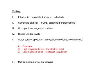
Target Hall Layout Outline Chris Densham (Brian Smith)
Constraints • Two Main Beam Lines 10 metres apart • Positron Source Beam lines • Target AMD Pre-Acceleration system A • Positron CAPture system A • Target AMD Pre-Acceleration System B • Positron Pre-Accelerator Positron Beam Lines 2.5 Metres apart
Initial Basis for Remote Handling • Water cooled Ti alloy target wheel assumed • Target changeover in hours - (short target lifetime) which indicates: • 2 parallel target stations and 2 hot cells • Modular approach - simple • Horizontal installation system considered (based on ISIS)
Target module outlineTarget wheel + solenoid(s) + vacuum vessel Size of System Target wheel 1 m radius – may need to increase 1 or 2 Capture Solenoids (0.54 m Radius) Vacuum Tank Width 2.7 metre Height 2.2 metre Depth 1.0 metre All dimensions approximate….. 2.7 m 1 m Quick-connects to beam pipe
Baseline target module concept Target module vacuum vessel contains: 1 m Radius Target Wheel (reduced, if possible, from original 2m) One (Two) Superconducting Solenoids Vacuum vessel sealed to beam pipe, e.g. using inflatable pillow seals Replacement of target and/or solenoids carried out in hot cell
Installation System • The ISIS Horizontal type layout has been used as the starting point • Baseline concept is for the complete target and services system to be on rails and moved in and out of the beam • Vertical installation may have some advantages (space, cost) but likely to be slower to change targets
Horizontal Installation & Layout • Two target stations on the same side of the beam • One target system in the beam • Other target system retracted to the maintenance position • NB gap in beam pipe needs to be plugged
Possible single target station – Plan View Remote handling cell Services trolley (target cooling, cryogenics for solenoids) Target module Service lines
Single Target Station - Side View Remote handling cell Services trolley (target cooling, cryogenics for solenoids) Target module Service lines
Target hall layout 50 m UPT Target AMD Pre-Acceleration system B (in operation) Electron linac Target AMD Pre-Acceleration system A (Target module withdrawn into hot cell)
Issues to consider • Large size of target hall: high cost • Intersecting tunnels or open plan? • Location of cranes? • Access shaft • Storage area • Disposal of failed targets • Separate target and solenoid support and installation?
If target lifetime is many months or years… Target station design philosophy may change: • Target changeover in days or weeks • single target station and single hot cell may become possible • Modular approach still favoured • Vertical installation system may be possible • Less space required? – cheaper?
Future positron target work • Baseline positron target design needs eddy current analysis and lots more • UK hasn’t done any yet • But we have the tools to do this sort of thing…
Compressor Development - Analysis An example of some recent magnetic field modelling work – an eddy current analysis by Jim Rochford.