Download

1 / 231
2.41k likes | 2.76k Vues
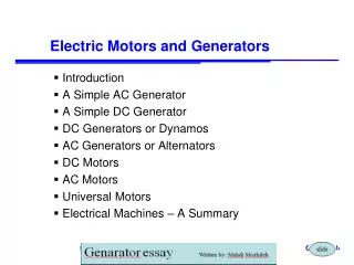
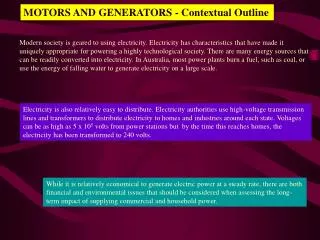
Motors and Generators. Magnetic Fields - Review. Magnetic fields are produced by magnetised magnetic materials such as iron electric currents. I. Magnetic Fields - Review. Magnetic Fields - Review. A magnetic material contains magnetised regions called domains.

E N D
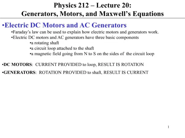
Magnetic Fields - Review • Magnetic fields are produced by • magnetised magnetic materials such as iron • electric currents I
Magnetic Fields - Review A magnetic material contains magnetised regions called domains • if the magnetic domains are randomly oriented, the material is not magnetised • if the magnetic domains become aligned, for example due to an external magnetic field, the material becomes magnetised
Magnetic Fields - Review • The magnitude of the magnetic field produced by an electric current depends on • the magnitude of the current - the greater the current, the stronger the magnetic field • the distance from the conductor - the greater the distance from the wire, the weaker the magnetic field • the shape into which the conductor is formed - e.g. a coil
Magnetic Fields - Review • Magnetic fields are represented by magnetic lines of force • direction of the field - indicated by an arrow pointing in the direction in which the north pole of a magnet points in the field • magnitude of the field - indicated by the spacing of the field lines - closer spacing represents a stronger field
Magnetic Fields - Review X X X X X X X X X X X X Magnetic fields are represented by • arrows - closer spacing stronger B field • crosses – representing a field into the page • dots – representing a field out the page
Magnetic Fields - Review Bar magnet Solenoid Straight conductor
Magnetic Fields - Review Remember the directions using the right hand grip rule - but NEVER quote this rule in the exam - it is just a memory aid! Straight conductor
Magnetic Fields - Review Remember the directions using the right hand grip rule - but NEVER quote this rule in the exam - it is just a memory aid! Animations - see RHRule.avi MagneticFieldWire.avi
Magnetic Fields - Review X X X X X X X X X X X X X X X X X X X X X X X X X The magnetic field “close to” the end of a bar magnet is uniform S N B
Magnetic Fields - Review X X X X X X X X X X X X X X X X X X X X X X X X X B The magnetic field inside, and “close to” the ends of a solenoid is uniform
Background - the cathode ray tube e E A cathode ray tube (CRT) is a highly evacuate glass tube containing a source of electrons (cathode), and in which there is a strong electric field created by a high voltage between the cathode and a positive electrode (anode) at the opposite end of the tube. Electrons travelling in straight lines through the vacuum, are accelerated from the cathode to the anode by an electric field, E
Background - the cathode ray tube A beam of electrons is called a cathode ray. Cathode rays are not visible, since electrons neither reflect or emit light under these conditions. A demonstration cathode ray tube contains a sloping phosphorescent screen, which emits light when electrons strike it, making the path of the electrons visible.
Background - the cathode ray tube Cathode ray tubes (CRTs) are a key component in devices including Television receivers Computer monitors Cathode ray oscilloscopes (CROs) Medical monitors and other scientific equipment based on the CRO
Moving charges experience a force X X X X X X X X X X v X X X X X X X X X X F X X X X X + Electric charges moving in a magnetic field experience a force except when they move parallel to the magnetic field The force is a maximum when the charge moves perpendicular to the magnetic field - in this case the magnetic field is into the page B The force is perpendicular to both the velocity direction and the magnetic field direction
Moving charges experience a force • The magnitude of the force depends on • the magnitude of the charge • the velocity of the charge • the magnitude of the field • the angle between the direction of the field and velocity
Moving charges experience a force Electric charges moving in a magnetic field experience a force except when they move parallel to the magnetic field • This effect is called the motor effect • It is the principle underlying the operation of • cathode ray tubes (used in TVs and computers) • electric motors and generators • loudspeakers
First-hand investigation of the motor effect X X X X X X X X X The motor effect can be demonstrated by placing a magnet near a cathode ray so that the field of the magnet is perpendicular to the velocity of the cathode rays The observed result, which demonstrates the motor effect is the deflection of the cathode ray, in a direction perpendicular to the magnetic field and to the direction of the cathode ray velocity
First-hand investigation of the motor effect X X X X X X X X X deflection e The motor effect can be demonstrated by placing a magnet near a current carrying wire so that the magnetic field is perpendicular to the direction of the current flow in the wire The observed result, which demonstrates the motor effect is the deflection of the wire, in a direction perpendicular to the magnetic field and to the direction of the current
Moving charges experience a force F = qvB This equation is not in the syllabus • The force on a charge moving in a magnetic field is at right angles to • the velocity of the particle • the magnetic field A constant magnitude force, which is always perpendicular to the velocity of a particle, results in the particle travelling in a circular path
Motion of charges in the Van Allen belts Charged cosmic rays encountering the magnetic field of the Earth experience a magnetic force, trapping them in regions called the Van Allen radiation belts Van Allen radiation belts
Motion of charges in the Van Allen belts The spiralling paths of the charged cosmic rays is a result of the particles having components of their motion parallel to the Earth’s magnetic field, which is unaffected by the field, and perpendicular to the field, which causes the particles to travel in circular paths. The combined effect is a spiralling path.
Motion of charges in the Van Allen belts High energy charged particles interact with the Earth’s atmosphere at high latitudes (polar regions) to produce auroras.
Moving charges experience a force B I • A force is produced on a current carrying conductor in a magnetic field, except when the conductor is parallel to the field. • The magnitude of the force depends on and is directly proportional to • the magnitude of the current, I • the magnitude of the magnetic field, B • the length of the conductor, l in the field • the sine of the angle between the field and the conductor F = BIl If the wire is at an angle to the field, the force is reduced by a factor of sin(q) q F = BIl sin(q)
Moving charges experience a force Calculate the maximum force on a conductor of length 5 cm in a magnetic field with an intensity of 2 x 10⁻⁴ T when the current in the wire is 200 milliamperes. The maximum force is exerted when the conductor is perpendicular to the field, and is give by the expression F = BIl Write the equation first! F = 2 x 10–4 x 200 x 10–3 x 5 x 10–2 F = 2 x 10⁻⁶ newtons The force is perpendicular to the current and the field directions
Moving charges experience a force What is the direction of the force on the wire? How could the force be doubled without altering the length of the wire? Note first The force is perpendicular to the current and the field directions Therefore it must be either into or out of the page Use whatever aid to memory you have decided to use… The force is into the page Since F = BIl, doubling either the current or the magnetic field strength would double the force on the wire.
Force between current carrying conductors I . . . X X X Bout . . . X X X Bin . . . force force X X X I A force is produced between two parallel current carrying conductors The force is a force of repulsion when the currents are in the opposite directions k = 2 x 10⁻⁷ NA–2
Force between current carrying conductors force force I . . . X X X Bout . . . X X X Bin . . . X X X I A force is produced between two parallel current carrying conductors The force is a force of attraction when the currents are in the same direction k = 2 x 10⁻⁷ NA–2
Force between current carrying conductors A force is produced between two parallel current carrying conductors • The magnitude of the force between the conductors is • proportional to the magnitude of the currents in each wire • inversely proportional to the distance between the wires • dependent on the magnetic properties of the medium between the wires The medium between the wires determines the value of the constant k = 2 x 10⁻⁷ NA–2 in air or a vacuum
Force between current carrying conductors A force is produced between two parallel current carrying conductors • The force is a force of repulsion when the currents are in the opposite directions (a) • The force is a force of attraction when the currents are in the same direction (b)
Moving charges experience a force Calculate the force between two straight conductors separated by a distance of 1.5 cm with a common length of 35 cm between them when the current in one wire is 200 milliamperes and the current in the other is in the opposite direction, with a magnitude of 5000 microamperes. Write the equation first! Then substitute values… F = 4.7 x 10⁻⁹ newtons The force is perpendicular to the current and the field directions
Moving charges experience a force Calculate the force between the side of a square coil consisting of 20 turns carrying a current of 2 A and a straight conductor sharing a common length of 25 cm and carrying a current of 3 A if the distance between them is 2 cm. Write the equation first! Then substitute values… F = 3 x 10⁻⁴ newtons The force is perpendicular to the current and the field directions
Moving charges experience a force Q1. What is the force between two parallel conductors carrying currents in opposite directions one centimetre apart if the current in one is 10 amperes, in the other is 5 amperes and the common length is 2 m? (Ans. 0.002 N, repulsion) Q2. If the distance between the wires was increased to 2 cm, what would be the new force between the wires? (use the fact that force and separation are inversely proportional) Write the equation first! Then substitute values… F = 0.002 newtons The force is one of repulsion
syllabus Torque A torque is a force which acts to produce a rotational effect or a moment. The magnitude of a torque, t depends on the • magnitude of the force, F • distance of the force from the point of rotation, d
+ + + + + + + + + + + + syllabus The motor effect - force on a current-carrying wire Consider a wire carrying a current across a magnetic field, B as shown The force on the moving charges in the wire is into the page[don’t say “down”] This produces a resulting force on the wire that is also into the page A wire carrying a current in a magnetic field experiences a force due to the movement of charges in the wire. The net result is called the motor effect
Q P syllabus Torque on a current-carrying loop A rectangular loop of wire carrying a current can be placed in a magnetic field so that the force on opposite sides of the loop results in a turning force about an axis between the two sides. The force on side WZ is into the page [never say “down” - it is ambiguous] The force on side XY is out of the page [never say “up” - it is ambiguous] The net result is a pair of moments creating a torque which, given a suitable mechanical arrangement, may result in the loop’s rotation about the axis PQ
Q P syllabus Torque on a current-carrying loop The force is measured in newtons The distance is measured in metres The torque is therefore in … newton metres (N.m)
A current-carrying coil A magnetic field A commutator A DC current source A brush Features of a DC electric motor A coil on which a torque is produced by the interaction of a current and a magnetic field can be arranged, with other components, to produce an electric motor The current in the loop produces a torque on the loop, causing it to rotate A DC electric motor converts electrical energy to mechanical energy
The importance of the commutator The coil in position (a) experiences a maximum torque. The torque causes rotation, clockwise viewed from above At the position (b), no torque is produced Inertia carries the coil past the position shown in (b) and the commutator reverses the current direction so that the torque direction remains the same and the coil continues to rotate.
B B B . . . x x x syllabus The importance of the commutator Figure (a) viewed from above The torque produced causes the coil to rotate clockwise Inertia causes the coil to rotate past the position (b) and the commutator reverses the current in the coil In position (b) there is no torque because there is no current
syllabus Principle of a DC electric motor The commutator in an electric motor is the moving component of a motor, which provides an electrical contact between the external circuit supplying the energy to the motor and the rotating armature of the motor. Contact is achieved through brushes made of carbon, which make contact with the commutator via a smooth contoured surface matching the brushes to the commutator.
Principle of a DC electric motor Commutator This photograph shows the commutator of a motor made using many coils The use of many coils, each in a different plane, results in a more uniform torque being produced. The invention of the commutator was important for the development of electric motors, since it is the device that allows the current in the coil to be reversed every 180° so that the torque is always in the same direction.
Principle of a DC electric motor A DC electric motor converts electrical energy to mechanical energy
Principle of a DC electric motor • A DC motor’s operation is based on the principle that a current carrying conductor placed in, and at right angles to, a magnetic field tends to move in a direction perpendicular to the magnetic lines of force • A rectangular coil of wire placed in a magnetic field such that two sides of the coil always carry a current perpendicular to the field will experience a torque due to the forces produced on the sides - the torque causes the coil to rotate • A DC motor is similar in construction to a DC generator • A DC motor may be made to act as a DC generator by mechanically turning the coil in the field (a DC generator is a DC motor operating “in reverse” - the energy transformation is reversed)