The MICE vacuum system
The MICE vacuum system. Presented by Mark Tucker at CM-39, 26 June 2014. Schematic diagram. The Distributed Backing Manifold. A long pipe (100mm internal diameter) to which high-vacuum (HV) systems are connected


The MICE vacuum system
E N D
Presentation Transcript
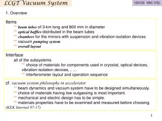
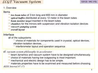
The MICE vacuum system Presented by Mark Tucker at CM-39, 26 June 2014
The Distributed Backing Manifold • A long pipe (100mm internal diameter) to which high-vacuum (HV) systems are connected • Evacuated by an Edwards iQ pump (500 m3/hr) ROOTS pump backed by a dry pump • Second iQ pump is spare (back-up when other is serviced or faulty) • Ultimate pressure of iQ pump is 2 x 10⁻³ mbar • iQ pumps are very clean, designed for semiconductor fabrication industry • iQ pump shaft seals are flushed with nitrogen gas from PEAK Scientific nitrogen generators
Expected pressure in backing manifold • Pipe of diameter d = 100mm has length, L = 20 metres • Under typical operating conditions (backing TMPs with cryostats at low pressure) expect molecular flow close to iQ pump, where d.p< 0.06 mbar.cm, and Knudsen flow (intermediate between laminar and molecular) closer to the HV rigs • Conductance increases with pressure so the system is stable • Under typical operating conditions, expect pressure to be < 2 x 10⁻² mbar at the end furthest from the pump
Expected backing pressure at TMP • HV pumping rigs connected to backing manifold by flexible hoses of 40mm internal diameter, approximately 1 to 2 metres long • Conductance of flexible hose less than conductance of main pipe if hose length > 1.3m • Expect typical backing pressures at TMP during pump-down to be < 0.15 mbar if hose is 2m long. This pressure will be lower during normal running due to low flow rates.
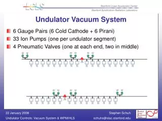
Module HV pumping rigs (schematic) Module Pumping Rigs (pipework)
Venting Venting of the systems must comply with STFC Safety Code No 33 (Safety of pressure and vacuum systems). Hence over-pressure valves, mechanical gauges and dedicated vent valves have been included. The leak test port is not to be used for venting. Over-pressure protection is provided by bursting disks connected directly to the main vessels and the pumping line between the vessel and any valve.
System description Module (SS/FC) pumping system • Initial rough pumping of the modules from atmospheric pressure to 0.5mbar is provided by scroll pumps (typically 10m3/hr) to avoid damage to vessel MLI by excessive viscous flow. Below 0.5mbar, the system will automatically switch over to the main backing line with the 500m3/hrpump. • Pressure monitoring will be provided by wide range gauges with magnetic shielding. • At a predefined pressure the turbo pump will be turned on and the isolating valve opened, the by-pass valve will be closed automatically and maximum pumping will have been achieved. • Vacuum leak detection will be carried using a leak detector which can be connected to one of the many leak detection ports as and when required. Inter-space pumping system • Pumping will be provided by a dedicated scroll pump protected by a controlled isolation valve. No turbo pump is required. • Pressure monitoring and leak detection will be the same as described above.
Quench protection In the event of a rapid pressure rise to p > 6x10⁻³ mbar: • The valve SS?-Vac-Valve-01 will close to protect the turbo pump • The turbo pump will be switched off • The turbo bypass valve, SS?-Vac-Valve-02, will open to ensure pumping continues via Scroll-02. When the pressure decreases below 5 x 10⁻³ mbar: • Valve-01 will open • Valve-02 will close • The turbo pump will be switched on
If a TMP fails or is switched off, the associated SS-Vac-Valve-01 is closed • Gauges remain ON at all times
Pressure interlocks (Interface Vessel) • If SS?-Vac-Gauge-03 = atmospheric pressure and SS?-Vac-Gauge-04 = less than atmospheric pressure, then SS?-Vac-Valve-03 must remain closed. • This ensures that the Main Vessel can be pumped down even when the Interface Vessel is open to atmosphere/vented with N gas.
Pressure interlocks(Distributed Backing Manifold) On pump fail, or local power off, the associated valve RGH-Vac-Valve-01/02 will close. RGH-Vac-Valve-01/02 can only be opened if either: • RGH-Vac-Gauge-01/02 and RGH-Vac-Gauge-03 are both at atmospheric pressure, or • RGH-Vac-Gauge-01/02 and RGH-Vac-Gauge-03 are both at p < 0.5mbar Whilst pumping from atmosphere to operational vacuum the pump’s associated valve RGH-Vac-Valve-01/02 should be open provided that RGH-Vac-Gauge-01/02 is less than RGH-Vac-Gauge-04
scenarios for system control 1) pump from atmosphere for complete step IV in beamline position. • Request status of all plant. Reset all plant to known initial conditions. • Ensure all pneumatic valves are open. Manual gate valve is open. • Ensure manual valves to backing lines are closed and distributed backing line is under vacuum. • Start scroll pump 01. • When pressure less than 0.5 mbar, open the manual valve to the distributed backing system. Close SS?-Vac-Valve-04. Leave Scroll-01 running to pump the interface vessel. • Wait until pressure in main vessel < 0.05 mbar, then close SS?-Vac-Valve-02, start turbo pump. • System is now under normal running
1a) In maintenance position (out of beam) • Manual gate-valve to the vessel will be closed • Connect to a portable pumping rig 1c) Interface vessel open to atmosphere • As 1), but with SS?-Vac-Valve-03 closed
2) Normal operation • Distributed backing system running continuously • If SS?-Vac-Valve-01 < 8 x 10⁻⁸ mbar, close SS?-Vac-Valve-01 (cryopumping mode) • Switch off turbo after 30 minutes, unless… • If SS?Vac-Valve-01 > 2 x 10⁻⁷ mbar, SS?-Vac-Valve-01 is closed, and turbo is off: switch on turbo • If SS?-Vac-Valve-01 > 2.5 x 10⁻⁷ mbar, turbo at full speed, and gauge-02 within a decade of gauge-01, open SS?-Vac-Valve-01
3) Failure modes • If computer failure occurs, the control system carries on as indicated by the pressure interlocks • If the control system fails, the computer will be unable to obtain status updates – alert operator of potential failure • If magnets quench, expect a fast pressure rise. Open SS?-Vac-Valve-02 if SS?-Vac-Gauge-01 pressure > RGH-Vac-Gauge-04. Turn turbo off.
4) Planned vent • Operator selects “Vent” mode on computer • Close SS?-Vac-Valve-01 • Stop Turbo • Close manual valve to distributed backing system • Open SS?-Vac-Valve-02 • Vent using manual venting procedure given in earlier slide
Computer software procedure • Check gauges are ON, no faults. • Check pressures and determine start-up procedure • Check of initial status and set MODE = • Pump-down from atmosphere • Test (pump-down of pumping system only, not vessels) • Pump re-start (system under vacuum) • Computer re-set (re-establishment of computer control on re-starting software – monitors only, until operator resets ability to control) • All text outputs written to the GUI, and all operator responses via the GUI, are written to a log-file complete with date and time of each entry.
Logic network Red = operator action
Timescale to completion Distributed Backing Manifold: end of July Individual pumping rigs: end of August High-vacuum pipes to vessels: end of September Control system ? Computer control software ? Services: • Electricity (single phase) ? • Electricity (three phase) ? • Water ? • Nitrogen gas (for venting) ? • Compressed air ?