2. Modeling with UML
2. Modeling with UML. Outline. History of Object Oriented Method More Object Oriented Concepts Modeling Concepts An Overview of UML UML Diagrams Case Study. 1. History of Object Oriented Method. 1.1The Growth of OO Methods.

2. Modeling with UML
E N D
Presentation Transcript
Outline • History of Object Oriented Method • More Object Oriented Concepts • Modeling Concepts • An Overview of UML • UML Diagrams • Case Study
1.1The Growth of OO Methods • In 1965 the first object-oriented (OO) programming language, Simula I, was introduced. • Almost immediately interest in OO design began to rapidly grow. • This led to the emergence of numerous competing OO design methods.
OO Analysis vs. OO Design • Analysis refers to understanding the problem. • Design refers to coming up with the solution. • Don’t confuse with broader use of word “design”
With all these design methods came numerous modeling languages. • By the early 90’s there were 50+ distinct OO modeling languages. • Darwinian forces in the marketplace led to three dominate methods, each having its own modeling language.
Object-oriented Design(OOD) Designing systems using self-contained objects and object classes
Objectives • To explain how a software design may be represented as a set of interacting objects that manage their own state and operations • To describe the activities in the object-oriented design process • To introduce various models that describe an object-oriented design • To show how the UML may be used to represent these models
Characteristics of OOD • Objects are abstractions of real-world or system entities and manage themselves • Objects are independent and encapsulate state and representation information. • System functionality is expressed in terms of object services • Shared data areas are eliminated. Objects communicate by message passing • Objects may be distributed and may execute sequentially or in parallel
Advantages of OOD • Easier maintenance. Objects may be understood as stand-alone entities • Objects are appropriate reusable components • For some systems, there may be an obvious mapping from real world entities to system objects
1.2 Three Dominant Methods • Object-oriented Analysis & Design (OOAD) – Grady Booch • The Object Modeling Technique (OMT) – Jim Rumbaugh • The Object-oriented Software Engineering method (OOSE) – Ivar Jacobson • Each one had its strengths and weaknesses.
(1) Booch (OOAD) • Very complex • The modeling language contained a formidable number of diagrams and resulting symbols • Allowed for effective low-level design and its fine grain detail was even useful for documenting code. • Good at OO design, weak at OO analysis
(2) Rumbaugh (OMT) • OMT had a simpler modeling language • It was better at higher-level designs than Booch Method. • Good at OO analysis, weak at OO design
(3) Jacobson (OOSE) • Major feature was “use classes” • Use classes model how a system interacts with users (which might be other systems or end users) • Viewing things from the user’s perspective drove the design process • This made it good at very high-level design.
Coming Together • Booch (OOAD) good at low-level design • Jacobson (OOSE) good at high-level design • Rumbaugh (OMT) good at the middle ground
Booch’s and Rumbaugh’s methods seemed to be evolving in a similar direction • In 1994 they joined forces in effort to merge their two methods • They both wanted to include use cases, so soon Jacobson joined them
Shortages • It became too difficult to successfully merge all three methods. • At same time, the software engineering community wanted an effective and standardized modeling language • The three then focused their efforts on unifying their three modeling languages
1.3 UML • In 1996 the Unified Modeling Language was introduced as UML 0.9 and then 0.91 • Input was obtained from many, including TI, IBM, Microsoft, Oracle, and HP. • This led to UML 1.0 in 1997 • Eventually, the semantics and flexibility was improved resulting in UML 2.0 in 2003
Since its publication in 1991, the UML has been enhanced based on the work of many different authors.
* * System Model View depicted by described by airplane:System scaleModel:Model flightSimulator:Model blueprints:View fuelSystem:View electricalWiring:View UML
Systems, Models, and Views • A model is an abstraction describing system or a subset of a system • A view depicts selected aspects of a model • A notation is a set of graphical or textual rules for representing views • Views and models of a single system may overlap each other
Application and Solution Domain • Application Domain (Requirements Analysis): • The environment in which the system is operating • Solution Domain (System Design, Object Design): • The available technologies to build the system
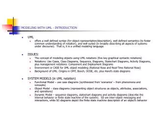
What is UML? • UML (Unified Modeling Language) • An emerging standard for modeling object-oriented software. • Resulted from the convergence of notations from three leading object-oriented methods: • OMT (James Rumbaugh) • OOSE (Ivar Jacobson) • Booch (Grady Booch) • Reference: “The Unified Modeling Language User Guide”, Addison Wesley, 1999. • Supported by several CASE tools • Rational ROSE • Together/J • ...
UML is for Visual Modeling A picture is worth a thousand words! Uses standard graphical notations Semi-formal Captures Business Process from enterprise information systems to distributed Web-based applications and even to hard real time embedded systems Sales Representative Places Order Customer Fulfill Order Item via Ships the Item Business Process
3.2 UML is also for … Specifying • Building models that are: Precise, Unambiguous, Complete • UML symbols are based on well-defined syntax and semantics. • UML addresses the specification of all important analysis, design, and implementation decisions. Constructing • Models are related to OO programming languages. • Round-trip engineering requires tool and human intervention to avoid information loss • Forward engineering— direct mapping of a UML model into code. • Reverse engineering— reconstruction of a UML model from an implementation. Documenting • Architecture, Requirements, Tests, Activities (Project planning, Release management)
3.3 Architecture & View UML is for visualizing, specifying, constructing, and documenting with emphasis on system architectures (things in the system and relationships among the things) from five different views Architecture -A set of significant decisions Design View Implementation View vocabulary functionality system assembly configuration mgmt. Use Case View behavior Process View Deployment View system topology distribution delivery installation performance scalability throughput
3.4 Three basic building blocks of UML • Things • important modeling concepts (individual ones as the primitive kinds) • Relationships • tying individual things (i.e., their concepts) • Diagrams • grouping interrelated collections of things and relationships UML=Things+Relationships+Diagrams
3.4.1 Things Structural — nouns of UML models. Behavioral — dynamic (verbal) parts of UML models. Grouping — organizational parts of UML models. Annotational — explanatory parts of UML models. Things=Structural+Behavioral+Grouping+Annotational
(1) Structural Things in UML Nouns of UML models. Conceptual or physical elements. Active Class Class Collaboration Event Mgr thread time suspend( ) flush( ) stop( ) Window origin size open( ) close( ) move( ) Node Chain of Responsibility WebServer Place Order listbox IWindow Interface Component Use Case
(2) Behavioral Things in UML Verbs of UML models. Dynamic parts of UML models: “behavior over time and space” Usually connected to structural things in UML. Two primary kinds of behavioral things: Interaction behavior of a set of objects comprising of a set of message exchanges within a particular context to accomplish a specific purpose. display State Machine behavior that specifies the sequences of states an object or an interaction goes through during its lifetime in response to events, together with its responses to those events. Idle Waiting
(3) Grouping Things in UML Packages - one primary kind of grouping. - General purpose mechanism for organizing elements into groups. - Purely conceptual; only exists at development time. - Contains behavioral and structural things. - Can be nested. - Variations of packages are: Frameworks, models, & subsystems. Meeting Scheduler
(4) AnnotationalThings in UML Explanatory parts of UML models Comments regarding other UML elements (usually called adornments in UML) Noteis one primary annotational thing in UML best expressed in informal or formal text. flexible drop-out dates
3.4.2 Relationships Dependency Association Generalization Realization
Dependency • A semantic relationship between two things in which a change to one thing (independent) may affect the semantics of the other thing (dependent). Directed is optional and label is optional.
Associations A structural relationship that describes a set of links, a link being a connection between objects. Can bedirected labelsCan havemultiplicity & role names employee employer 0..1 * Aggregation a special kind of association. It represents a structural relationship between the whole and its parts. Represented by a black diamond.
Realization • Asemantic relationship between two elements, wherein one element guarantees to carry out what is expected by the other element. Where? Between interfaces and classes that realize them… Between use cases and the collaborations that realize them...
3.4.3 Diagrams Graphical representation of a set of elements. Represented by a connected graph: Vertices are things; Arcs are behaviors. 5 most common views built from 9 diagram types. • ClassDiagram; Object Diagram • Use case Diagram • Sequence Diagram; Collaboration Diagram • StatechartDiagram • ActivityDiagram • Component Diagram • Deployment Diagram
:SimpleWatch :LCDDisplay :Time :WatchUser pressButton1() blinkHours() pressButton1() blinkMinutes() pressButton2() incrementMinutes() refresh() pressButtons1And2() commitNewTime() stopBlinking() Sequence Diagram Object Message Activation Sequence diagrams represent the behavior as interactions
Increment Hours button2Pressed button1&2Pressed Blink Hours button1Pressed Increment Minutes button2Pressed button1&2Pressed Blink Minutes button1Pressed Increment Seconds button2Pressed Blink Stop Seconds Blinking StatechartDiagrams State Initial state Event Transition Final state button1&2Pressed
Diagrams and System Model: • Functional model: Use case diagram • Object model: Class diagram • Dynamic model: Sequence diagrams, statechart, activity diagrams
Diagrams covered in this talk • Use case diagrams • Describe the functional behavior of the system as seen by the user • Class diagrams • Describe the static structure of the system: Objects, attributes, associations • Interaction diagrams • Describe the dynamic behavior between objects of the system • Statechart diagrams • Describe the dynamic behavior of an individual object • Activity diagrams • Describe the dynamic behavior of a system, in particular the workflow. • Package Diagrams • Describe the groupings of elements
An Actor represents a role, that is, a type of user of the system Passenger PurchaseTicket 4.1 Use Case Diagrams Used during requirements elicitation and analysis to represent external behavior (“visible from the outside of the system”) A use case represents a class of functionality provided by the system Use case model: The set of all use cases that completely describe the functionality of the system.
Use Case Diagrams Package SimpleWatch Actor ReadTime SetTime WatchUser WatchRepairPerson Use case ChangeBattery Use case diagrams represent the functionality of the system from user’s point of view
An actor is a model for an external entity which interacts (communicates) with the system: User External system (Another system) Physical environment (e.g. Weather) An actor has a unique name and an optional description Examples: Passenger: A person in the train GPS satellite: An external system that provides the system with GPS coordinates. Passenger 4.1.1 Actors Optional Description Name
• A use case represents a class of functionality provided by the system • Use cases can be described textually, with a focus on the event flow between actor and system • The textual use case description consists of 6 parts: Unique name Participating actors Entry conditions Exit conditions Flow of events Special requirements. PurchaseTicket 4.1.2 Use Case
4.1.3 Communication Relationships • Actors and use cases communicate when information is exchanged between them
4.1.4 Use Case Description • Brief use case -- consists of a few sentences summarizing the use case • Casual use case -- consists of a few paragraphs of text, summarizing the use case. • Fully dressed use case -- a formal document based on a detailed template with fields for various sections; and it is the most common understanding of the meaning of a use case.