Download
1 / 34
350 likes | 474 Vues
Explore the manipulation of degenerate quantum gases, specifically Bose-Einstein condensates, on atom chips. Discover the developments, applications, and techniques used to study these ultra-cold atomic systems. Learn about interferometry, atom interferometers, and multipath interferometry on atom chips. Dive into the results and conclusions of experiments involving degenerate atoms. Gain insights into the production, cooling, and manipulation of atoms in these systems. This field offers exciting opportunities for fundamental physics research and applications in areas such as quantum information and sensor technology.

E N D
Degenerate Quantum Gasesmanipulation on AtomChips Francesco Saverio Cataliotti
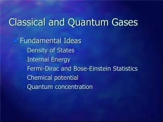
Outlook • Bose-Einsteincondensates on a microchip • AtomInterferometry • MultipathInterferometry on anAtomChip • Results and Conclusions
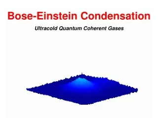
Temperatura Fermioni Bosoni T < TF T < TC EF Degenerate atoms
Degenerate Atoms 1925: Einstein predicts “condensation” of bosons 60’s: Development of Lasers 80’s: Development of laser cooling 1985: Magnetic Trapping of ultracold atoms 1986: Optical trapping of Na 1987: Na Magneto-Optical Trap 1995: First 87Rb Bose-Einstein Condensate • Huge playground for fundamental physics: • BEC with Li, Na, K, Cs, Fr… • Optical gratings, collective excitations… • First applications: • Interferometry • Earth and Space sensors • Quantum Information 2001: First BEC of 87Rb on an Atom Chip
10-20 T 300 K laser cooling 10-6 T 10 K evaporative cooling 2.6 T 100 nK Routeto BEC in dilutegases
MagnetoOptical Trap (MOT) trapping cooling
Forced evaporation in a magnetic trap (conservative potential) temperature Evaporative cooling remove highest velocities thermalization through elastic collisions cooling
BEC on a chip I Macroscopictrap Micro-trap Current~ 100 A Power ~ 1.5 kW Current<1 A Power < 10 W n = 10-100 Hz n = 1-100 kHz Ultra High Vacuum~ 10-11Torr High Vacuum~ 10-9Torr double MOT system: Laser power~ 500 mW single MOT system: Laser power~ 100 mW Large BEC 106atoms but production cycle> 1 min BEC 105atoms and production cycle~ 1 s
s+ s- s+ s+ s- s- Laser Coolingcloseto a surface
BEC on a chip • Planar Geometry gold microstrips on silicon substrates Bwir (Iwir= 3A) Bbias= {0,3.3,1.2} Gauss |B| (Gauss) z (mm) Iwir= 3 A ; Bbias= {0,3.3,1.2} Gauss Iwir= 1 A ; Bbias= {0,3.3,1.2} Gauss |B| (Gauss) x (mm)
time [ms] action MOT in reflectionloading 10^8 atoms MOT transfer close to the chip (~1mm) CMOT + Molasses 5 x 10^7 atoms @ T ~ 10 μK Optical pumping Ancillarymagnetictrap (big Z wire) 20 x 10^6 atoms @ T ~ 12 μK Compression and transfer to the magnetictrap on chip (chip Z wire) 20 x 10^6 atoms @ T ~ 50 μK (~200 μm) Evaporation (big U under the chip) BEC with 30x10^3 atoms, Tc=0.5 μK End of the cycle 5000 BEC Generation Routine 5450 5485 5490 5740 8300 23000
lens atoms CCD camera Imagingcoldatoms
BEC on a chip MOT ~ 10^8 atoms Molassesphase ~ 5 x 10^7 atoms @ T ~ 15 uK First Magnetic Trap (big Z wire) ~ 20 x 10^6 atoms @ T ~ 12 uK Magnetic Trap on Chip (chip Z wire) ~ 20 x 10^6 atoms @ T ~ 50 uK Free fall of the BEC BEC ~ 20 x 10^3 atoms @ T < 0.5 uK
Outlook • Bose-Einsteincondensates on a microchip • AtomInterferometry • MultipathInterferometry on anAtomChip • Results and Conclusions
Atom Interferometer BEC – coherent form of matter , a wavepacket BEC 1 BEC 2 BEC 1,2 BEC 2 BEC 1,2 different spin states coupling mechanism BEC 1 BEC 1 Rabi pulse separation for measurement Stern-Gerlach experiment
Atomic Ramsey Interferometer- Theory - 2 Δ=ω 0 -ω ω ω0 Solve GPE for the BEC start from 1 mix two states let them evolve for time T Solve SE for 1 atom for the non-interacting BEC mix them up again
Rabi Oscillations Stern-Gerlach method Δ B mf=2 mf=2 mf=1 BEC mf=2 Tp time space - pulse BEC mf=1 Rabi frequency
Rabi Oscillation mf -2 -1 0 1 2 π/2 Rabi frequency ~ 50KHz
Experimental Scheme:Ramsey Interferometer π/2 π/2 mf=2 Δ B space mf=2 mf=1 mf=2 mf=1 time
Ramsey Interferometer Oscillation frequency = 1/RF = 1/650KHz = 1.5 μs
Outlook • Bose-Einsteincondensates on a microchip • AtomInterferometry • MultipathInterferometry on anAtomChip • Results and Conclusions
Parameters of the Interferometric Signal amplitude D’Ariano & Paris, PRA (1996) Resolution: Working range: background Sensitivity: Weihs et al., Opt. Lett. (1996)
Multi-Path interferometer W W W W Funnyenougnfor N>3 the system can beaperiodicsincefrequencies are incommensurable Even more funthey are the solutionsof a complex Fibonacci Polynomial
Multi-Path interferometer Theredoesnotexist a p/2 pulse. Toobtain the best resolutionfrom the interferometeronehastooptimizepulse area
Outlook • Bose-Einsteincondensates on a microchip • AtomInterferometry • MultipathInterferometry on anAtomChip • Results and Conclusions
What can you use it for? Detection of a Light-Induced Phase Shift Polarisation σ+ Polarisation σ- Light-pulse detuning from F=2 F=3 was 6.8GHz.
Conclusions • We have demonstrated a compact time-domain multi-path interferometer on an atom chip • Sensitivity can be controlled by an RF pulse acting as a controllable state splitter. • Resolution superior to that of an ideal two-path interferometer. • Simultaneous measurement of multiple signals at the output enables a range of advanced sensing applications in atomic physics and optics • Integration of interferometer with a chip puts it into consideration for future portable cold-atom based measurement systems.
Thosewhoreallydidit Atom Chip Team our typical signal Ivan Herrera JovanaPetrovic Pietro Lombardi
Whodidit? A typical BEC JovanaPetrovic Ivan Herrera Pietro Lombardi